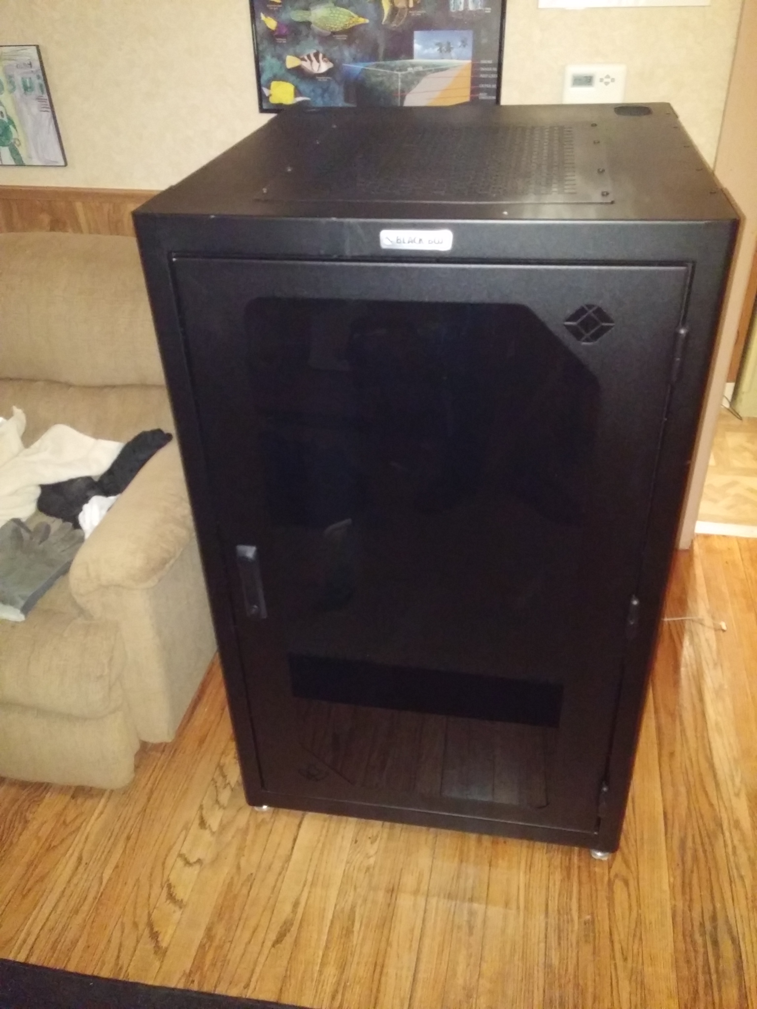
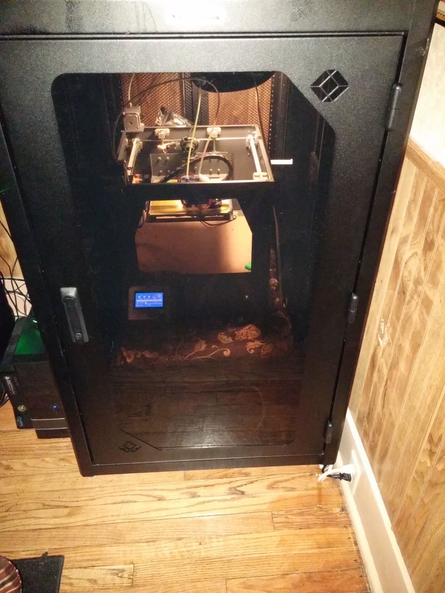
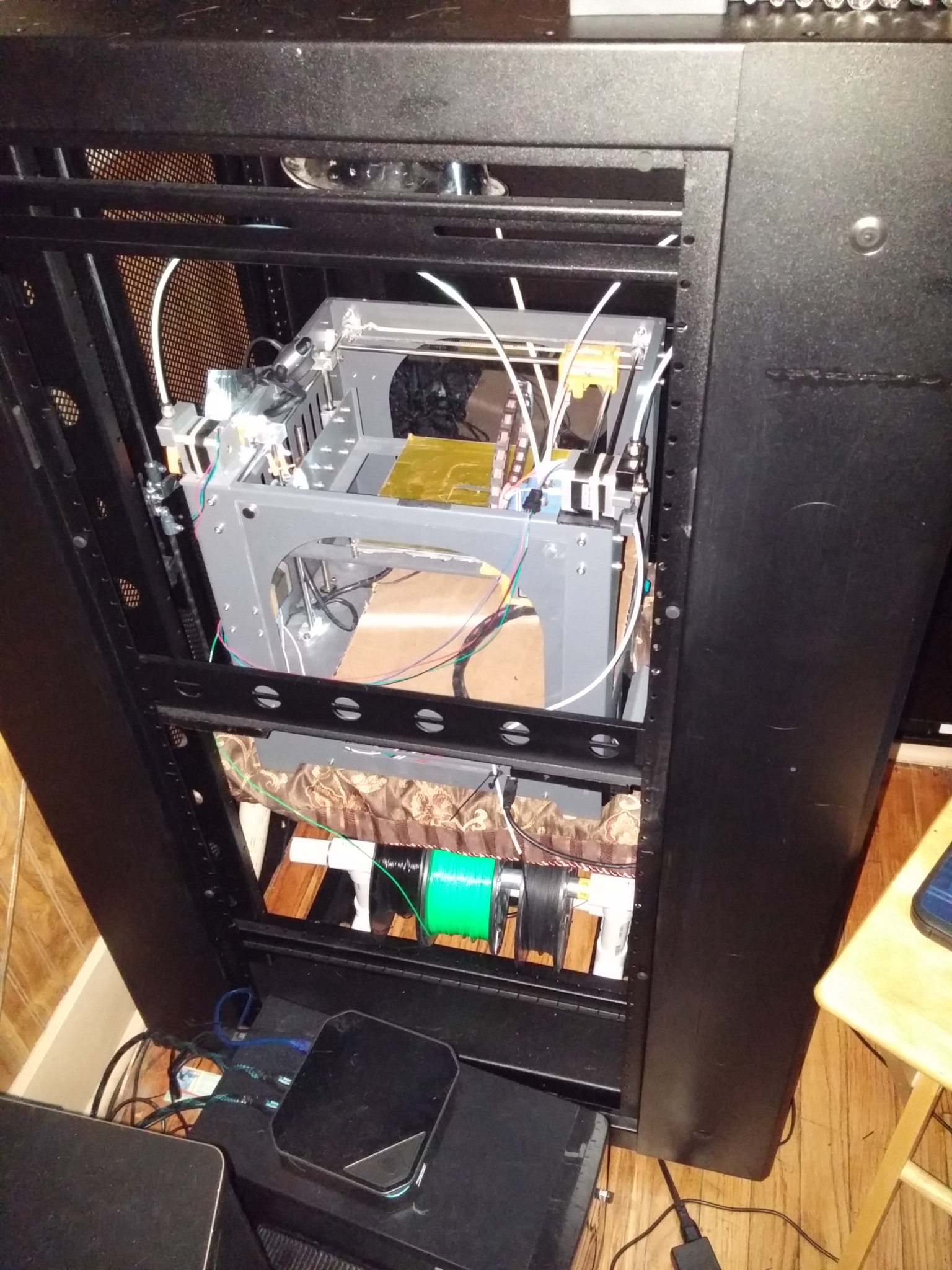
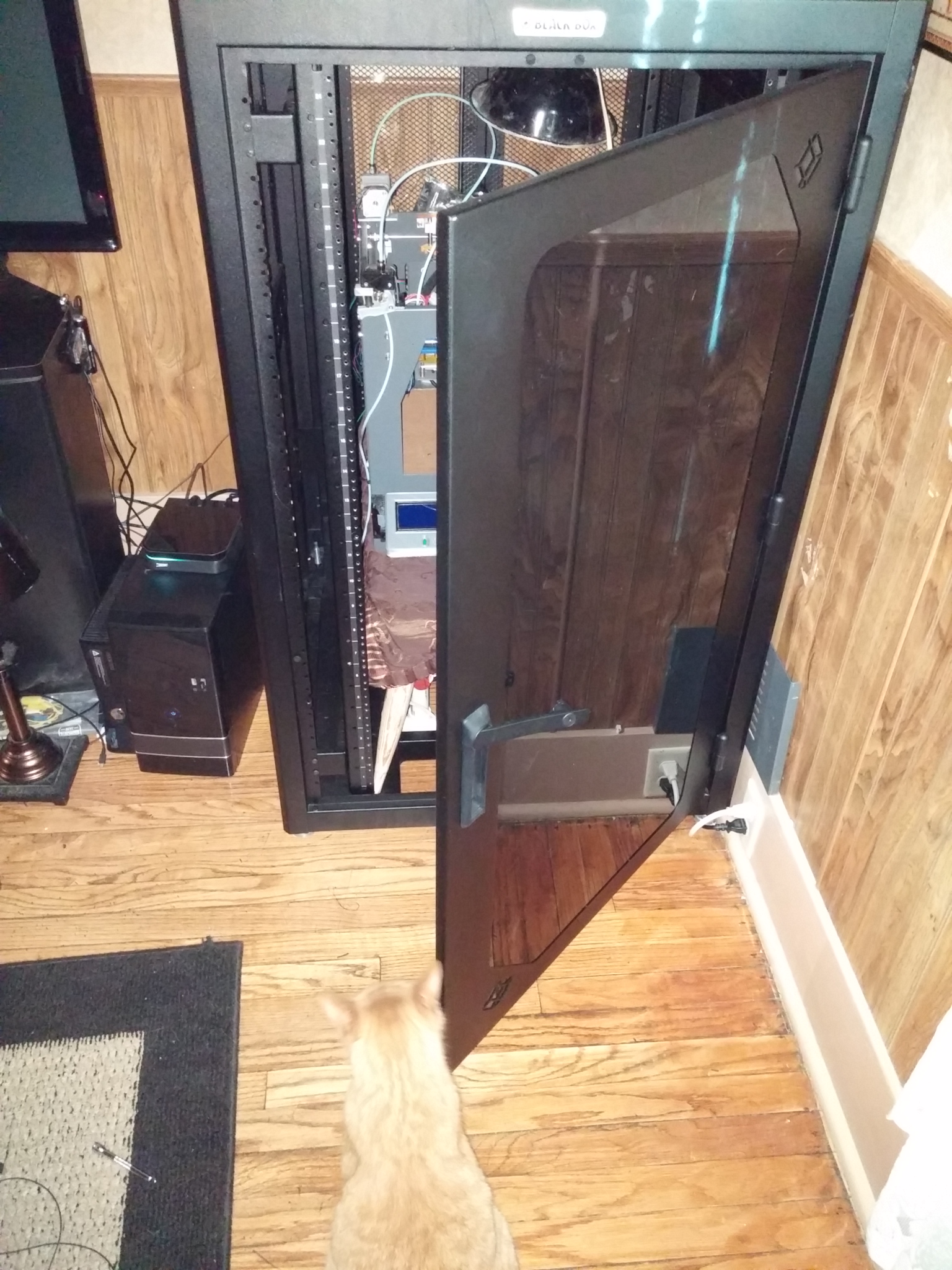
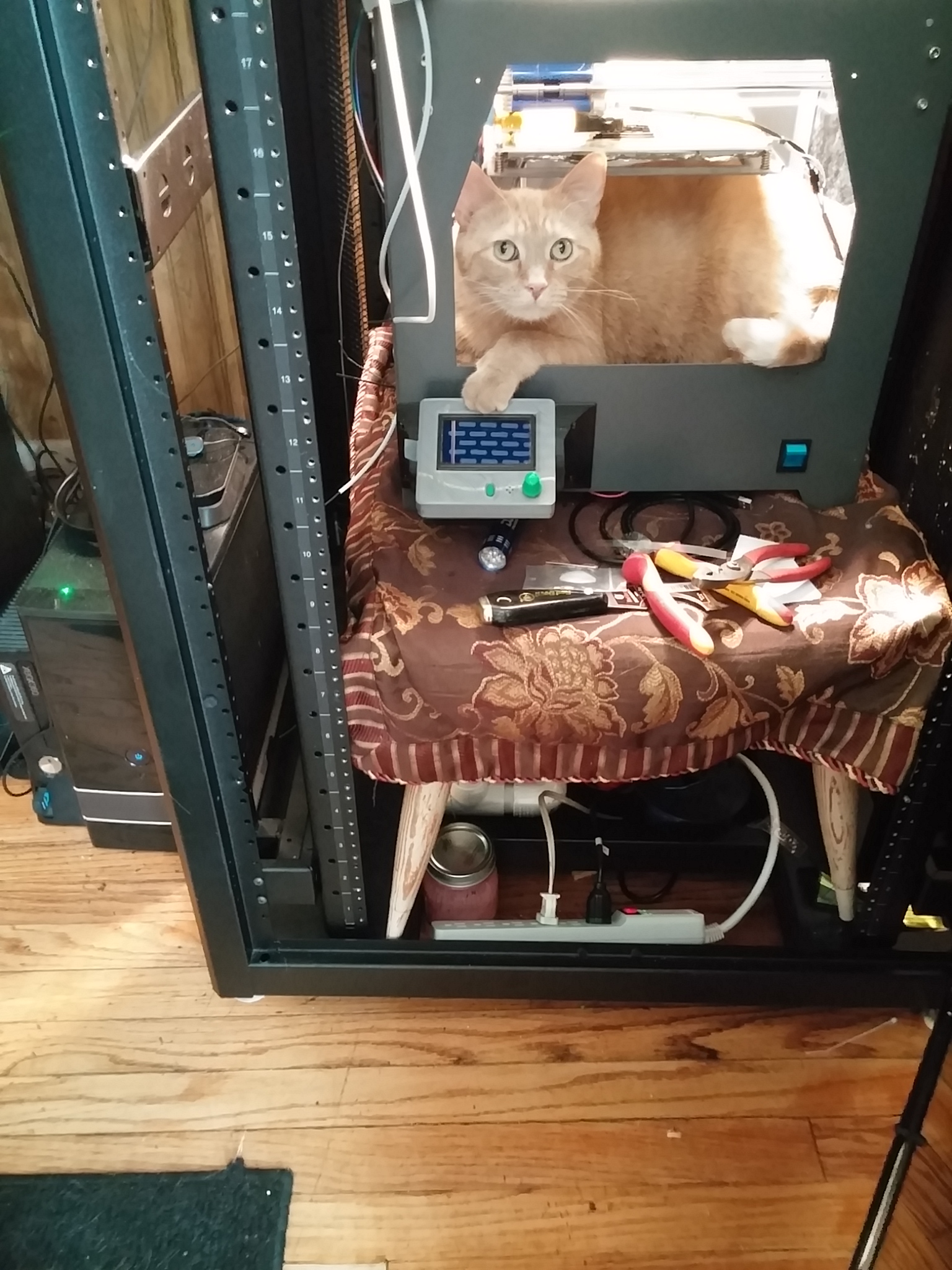
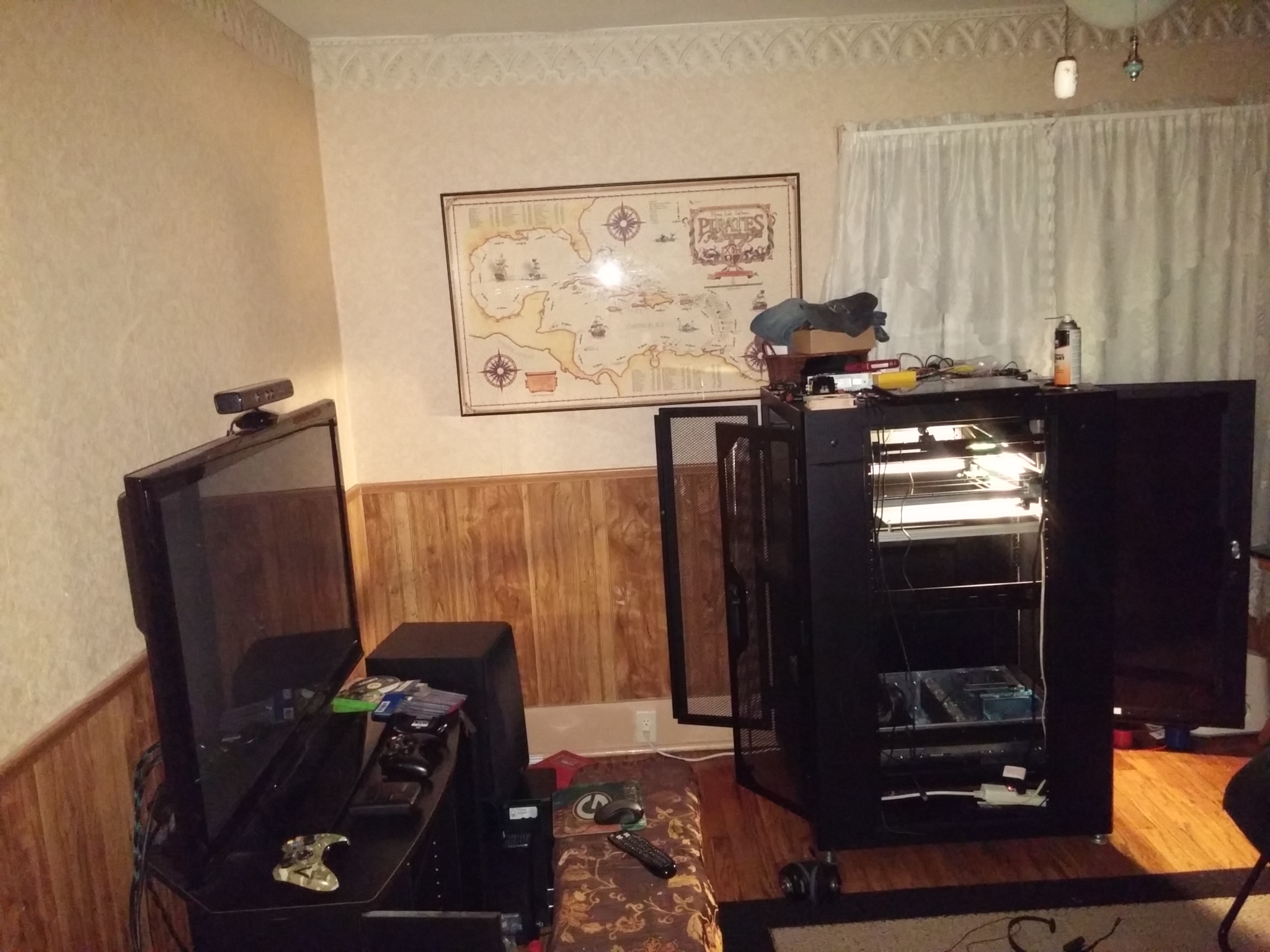
I got this server cabinet for my next 3D printer build which is a 32" X 32" X 48" BLACKBOX Data Cabinet. While I am getting all the parts and printing pieces for the new printer I found my current printer and table fit right inside. It has the added benefit of preventing my pets from trying to help by pawing at the printhead during prints. ☺
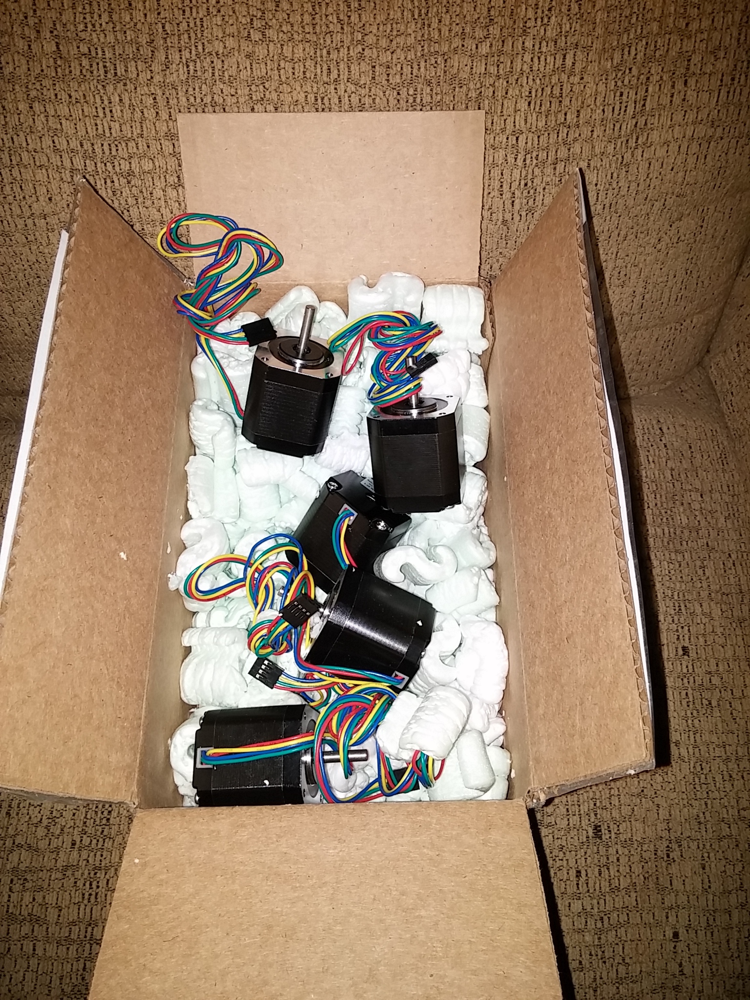
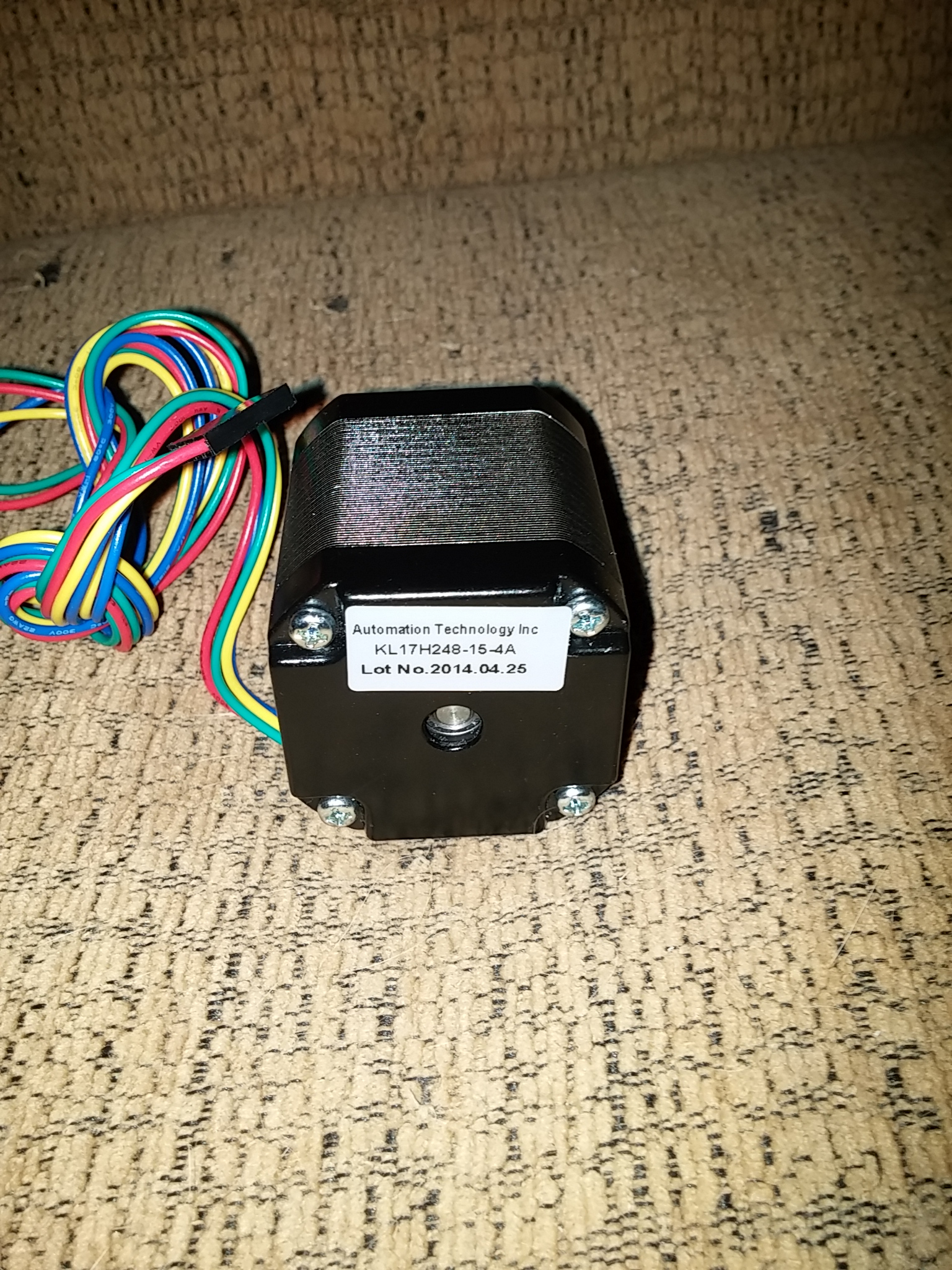
First batch of parts arrived today March 16, 2015 a set of stepper motors from Automation Technology Inc. Hoffman Estates, IL. Got the motors in 2 days with regular shipping so local helps with timing of the project. Need them to measure the mounts correctly and placement to keep them cool inside the cabinet. I keep changing the plan on how I want to build this printer, but right now the the X and Y motors will be at the top of the printer and have a shroud around them cooled by a fan. The print section separated from the elctronics so I can keep the print bed area warm.
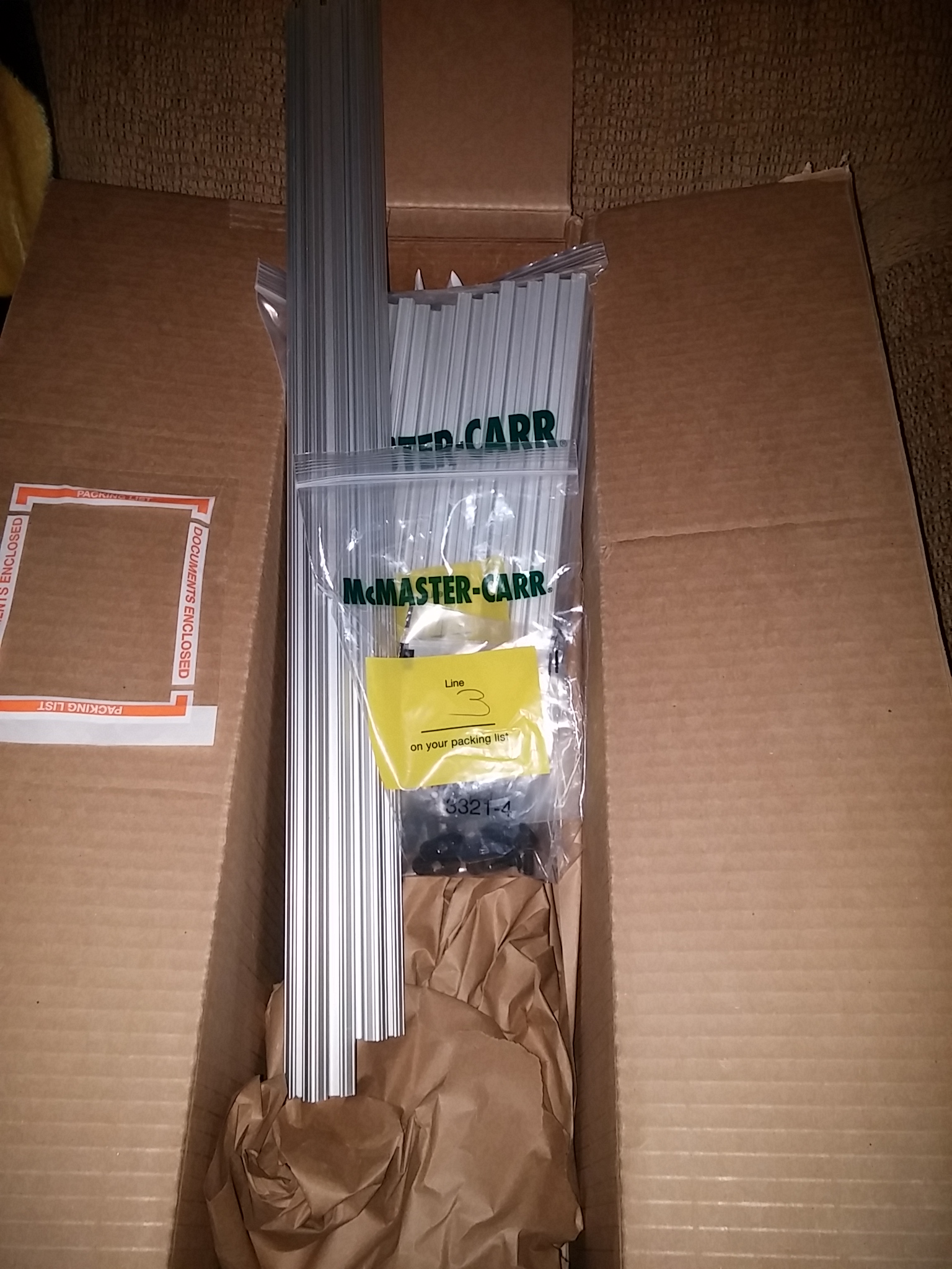
2nd package came in today March 17, 2015; 10 series T-Slotted Extrusion from McMaster-Carr Chicago, IL. This is for the build plate to mount to, essentially it will make a shelf that mounts to the Z Axis linear slides. I decided to get pieces cut to the lenghs I needed to eliminate any issues from me cutting them. The price was only a few extra dollars worth it for the time it would have taken me to cut them.
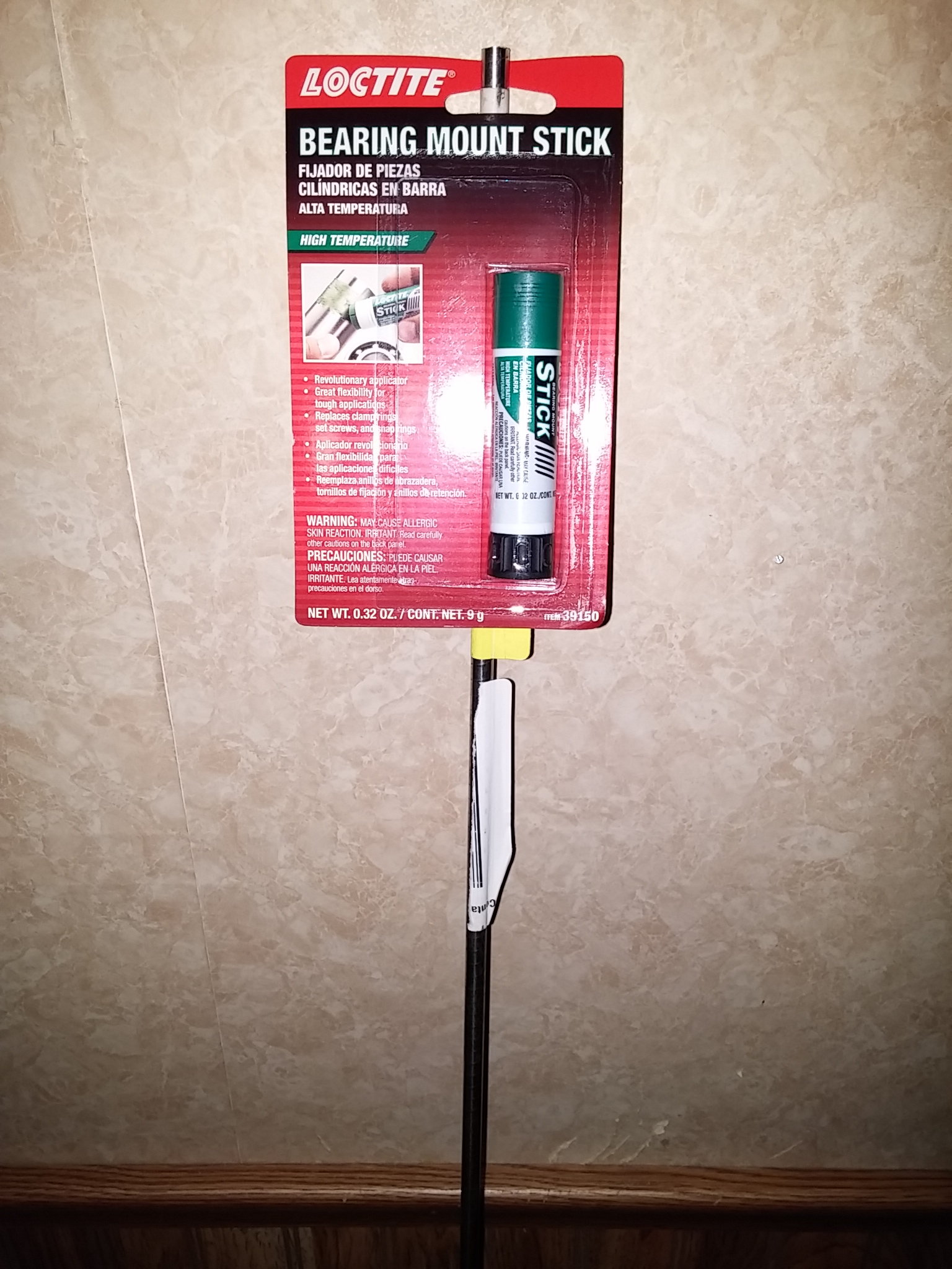
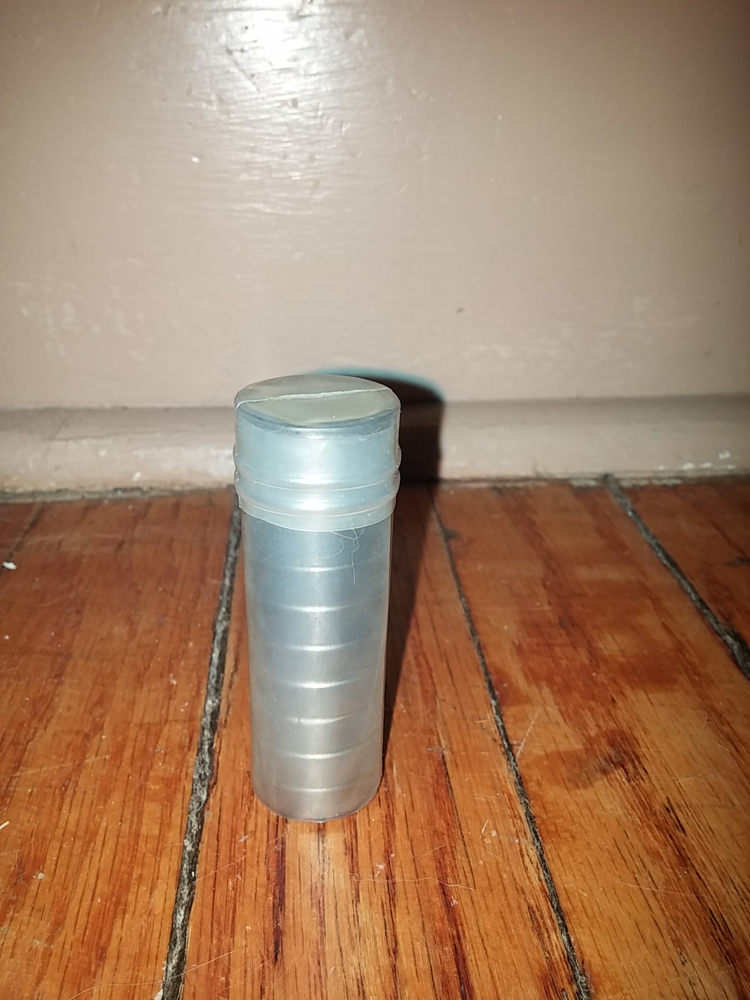
Today's package March 18, 2015; 8mm X 60" shaft and Loctite came in; I ordered them with Amazon Prime. I plan to cut the shaft in half and using for the drive shafts for the Y-axis. Kind of confusing to type out, but I plan on building it in a similar format to my current printer. I will post some close ups of it for reference when I get chance.
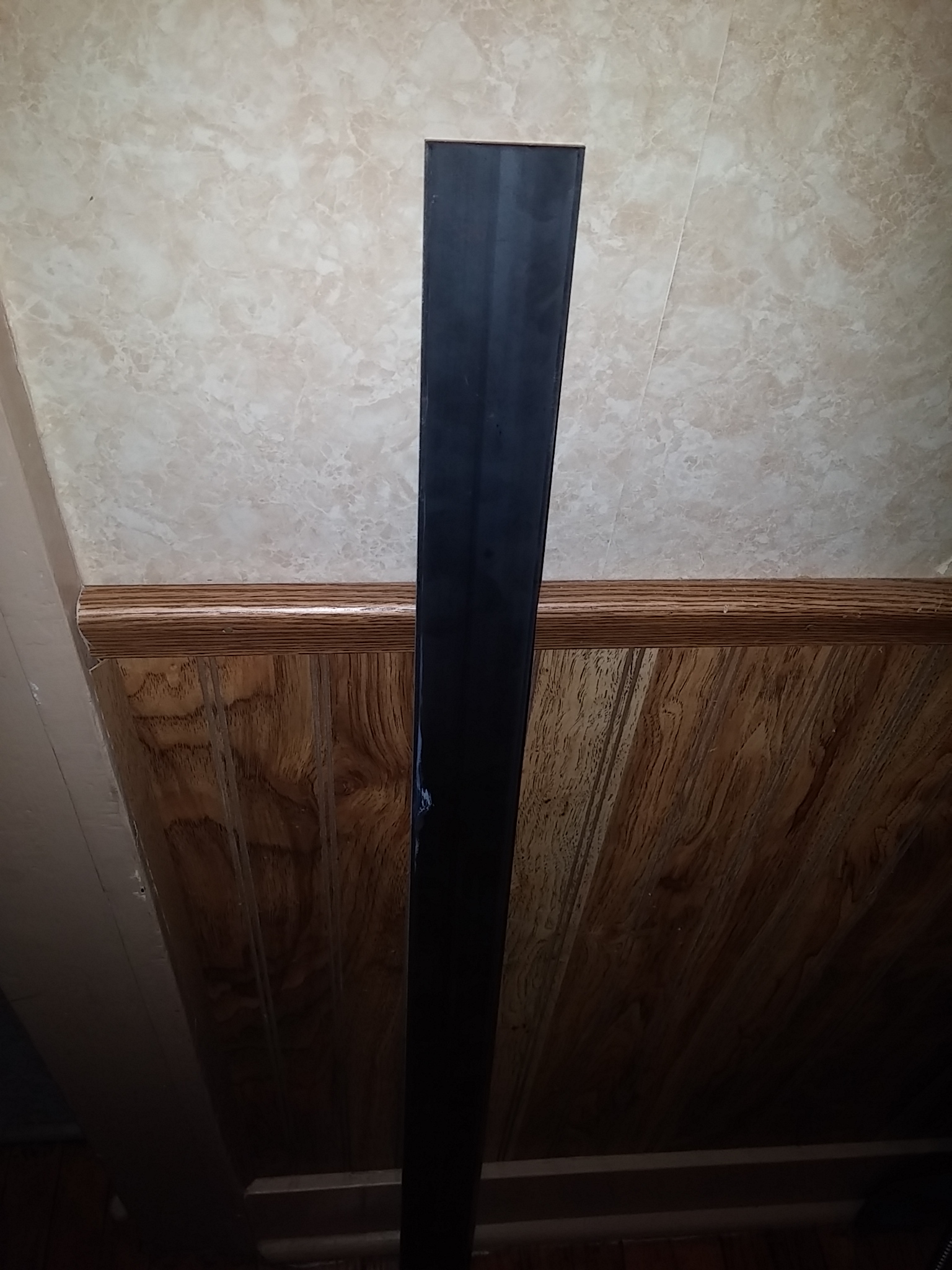
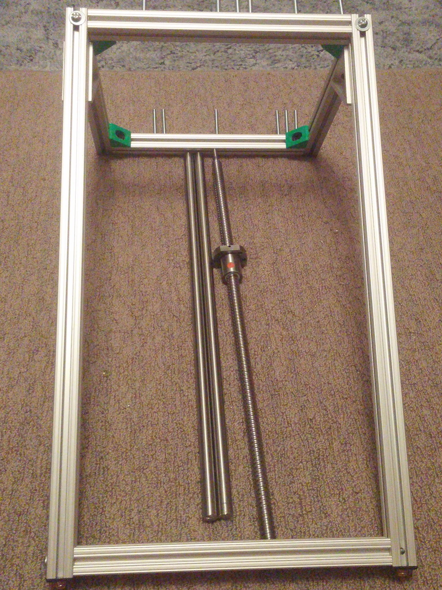
48" x 3" steel plate; I plan on cutting it on half and making two plates to mount all the Z-axis parts to. I will drill holes to match the rack mount holes making the entire Z-axis assembly removable as one unit. This will make it easy to service and upgrade later if needed.
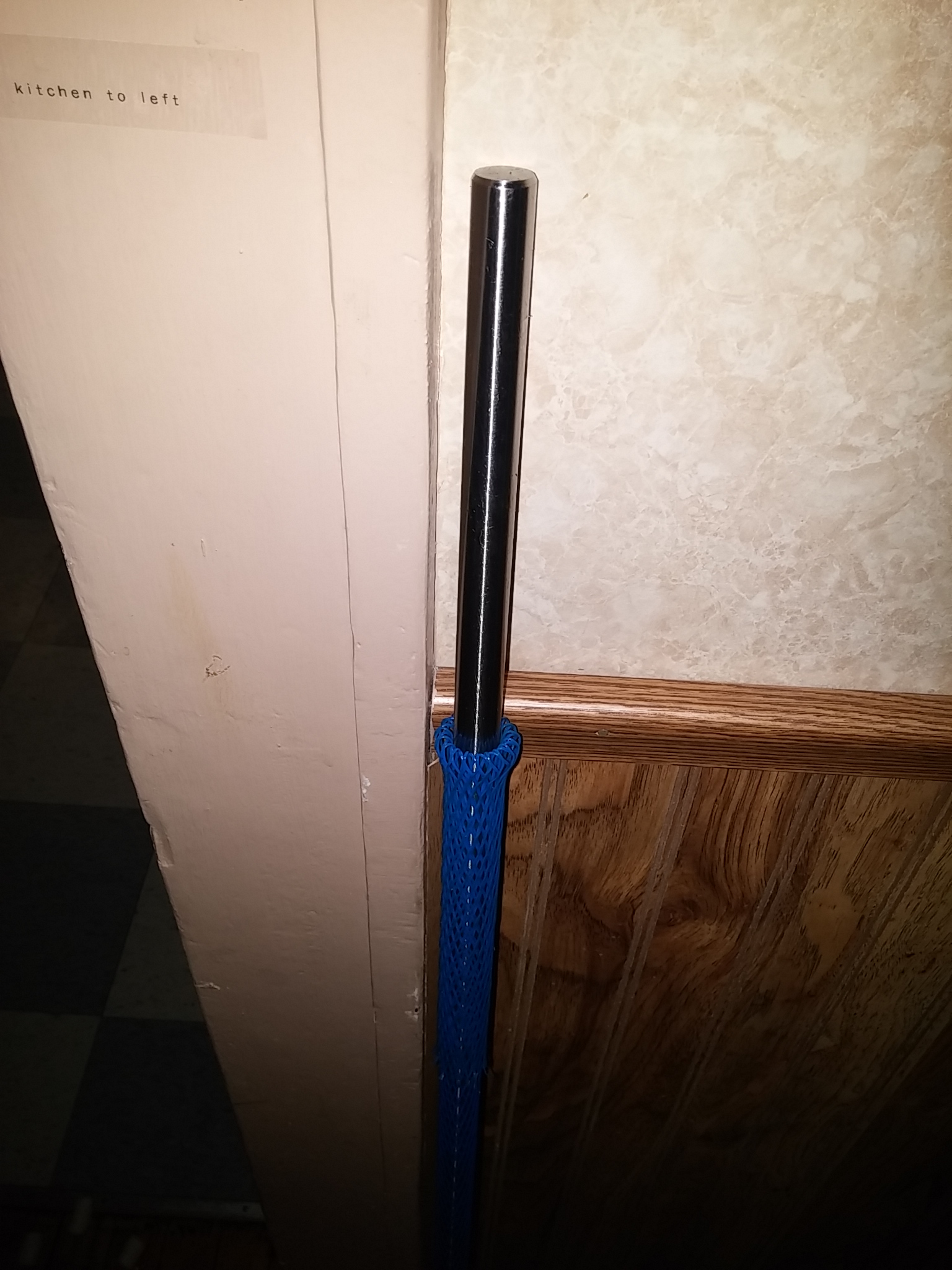
16mm shaft; I plan on cutting it in half and using for the Z-axis guide rods.
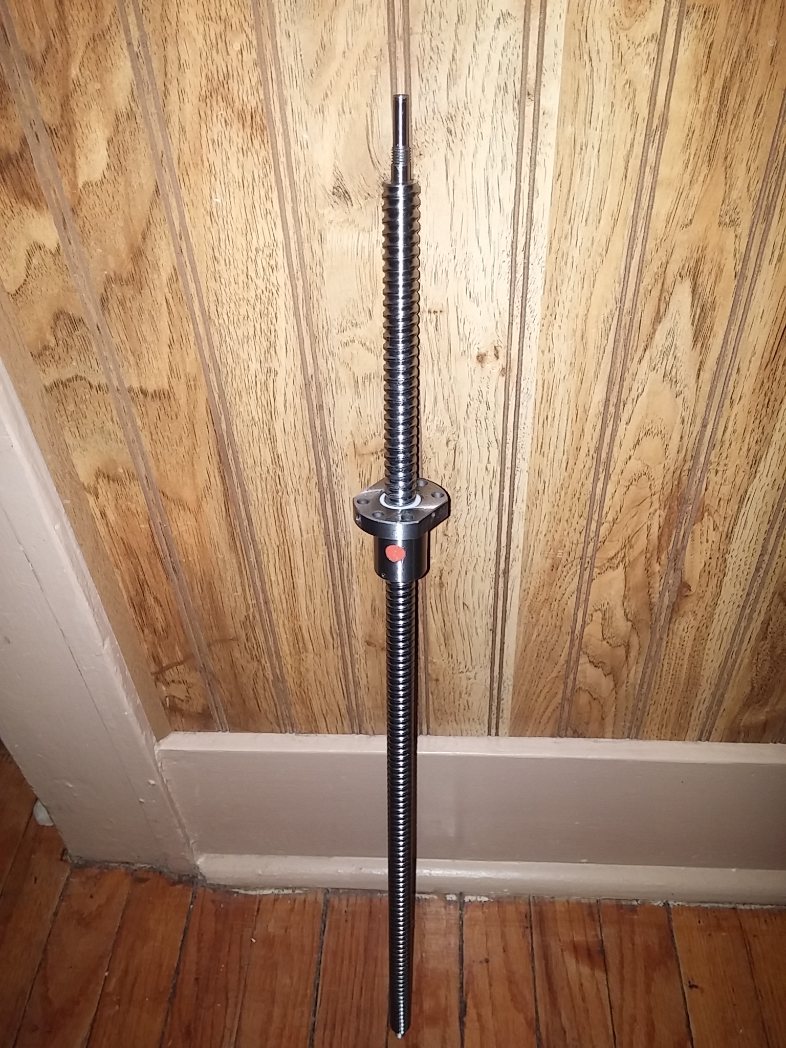
This is a 24" Ball screw for the Z-axis.
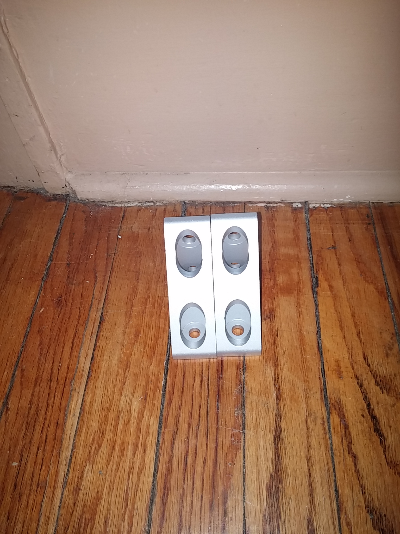
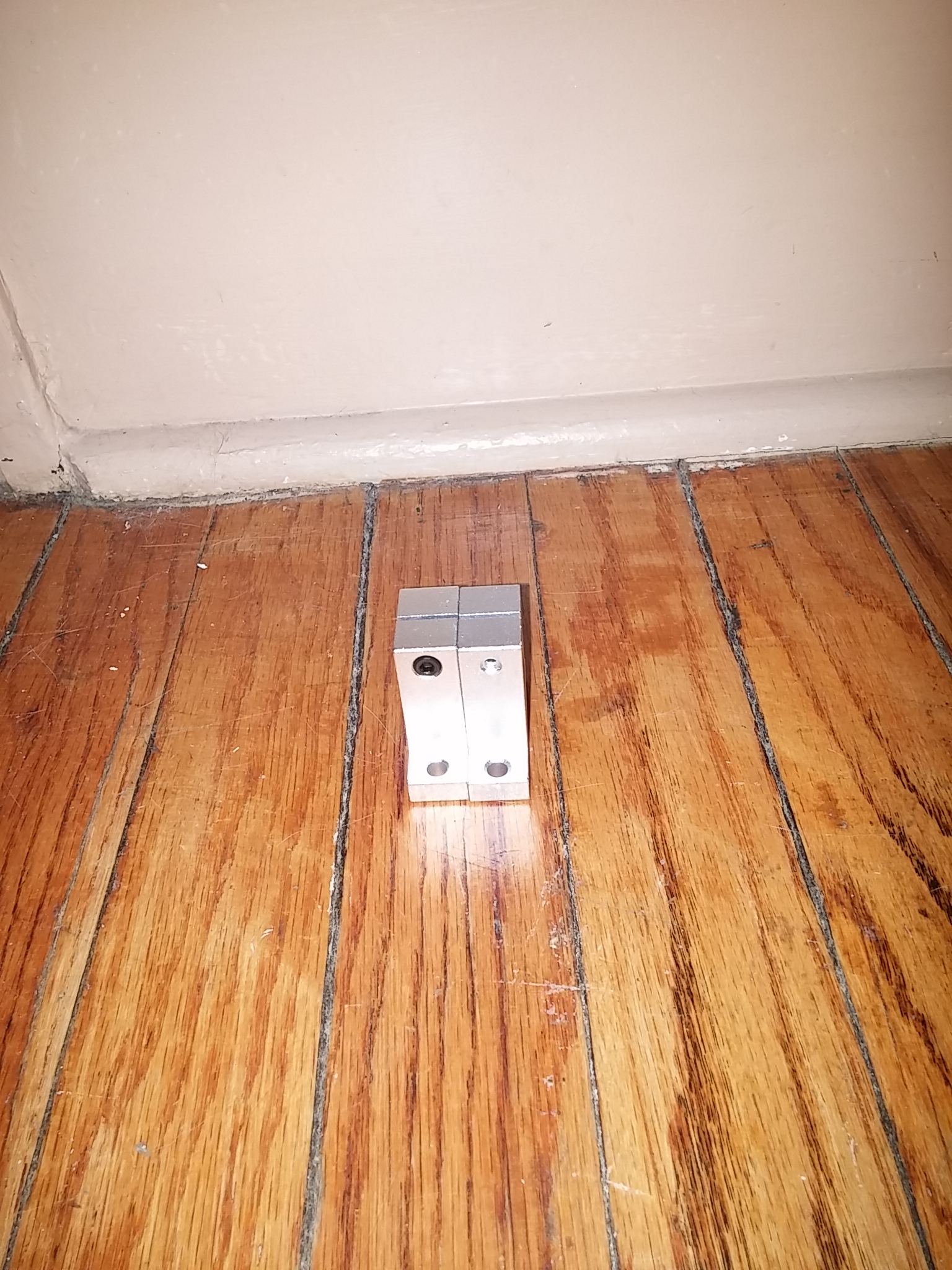
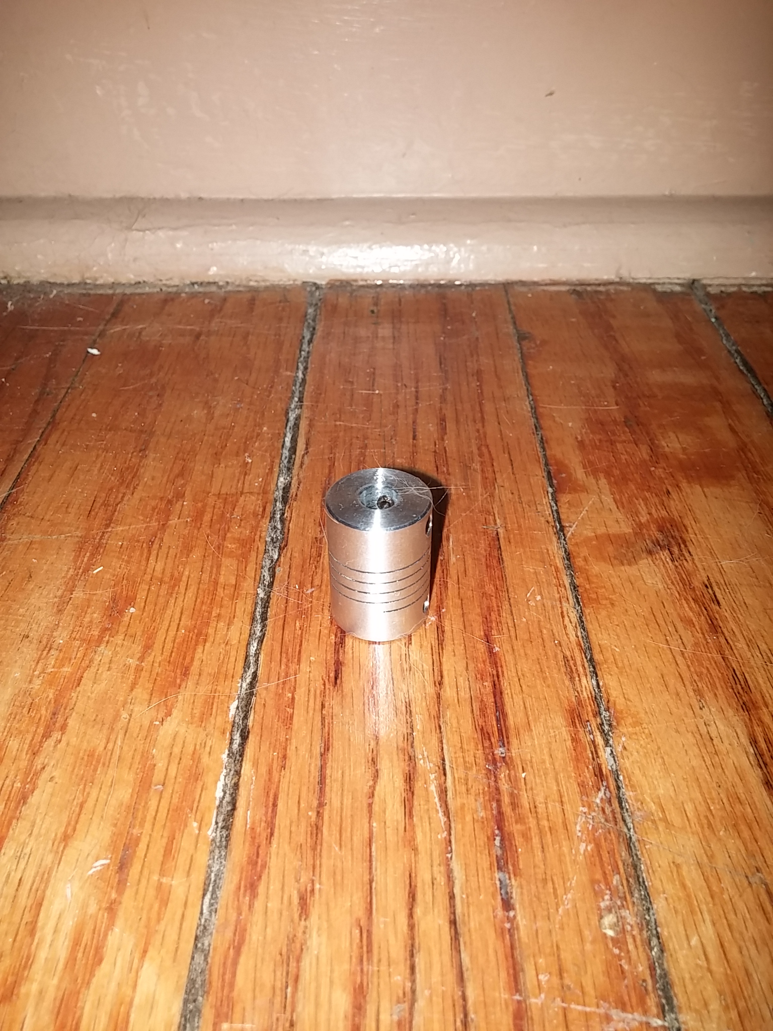
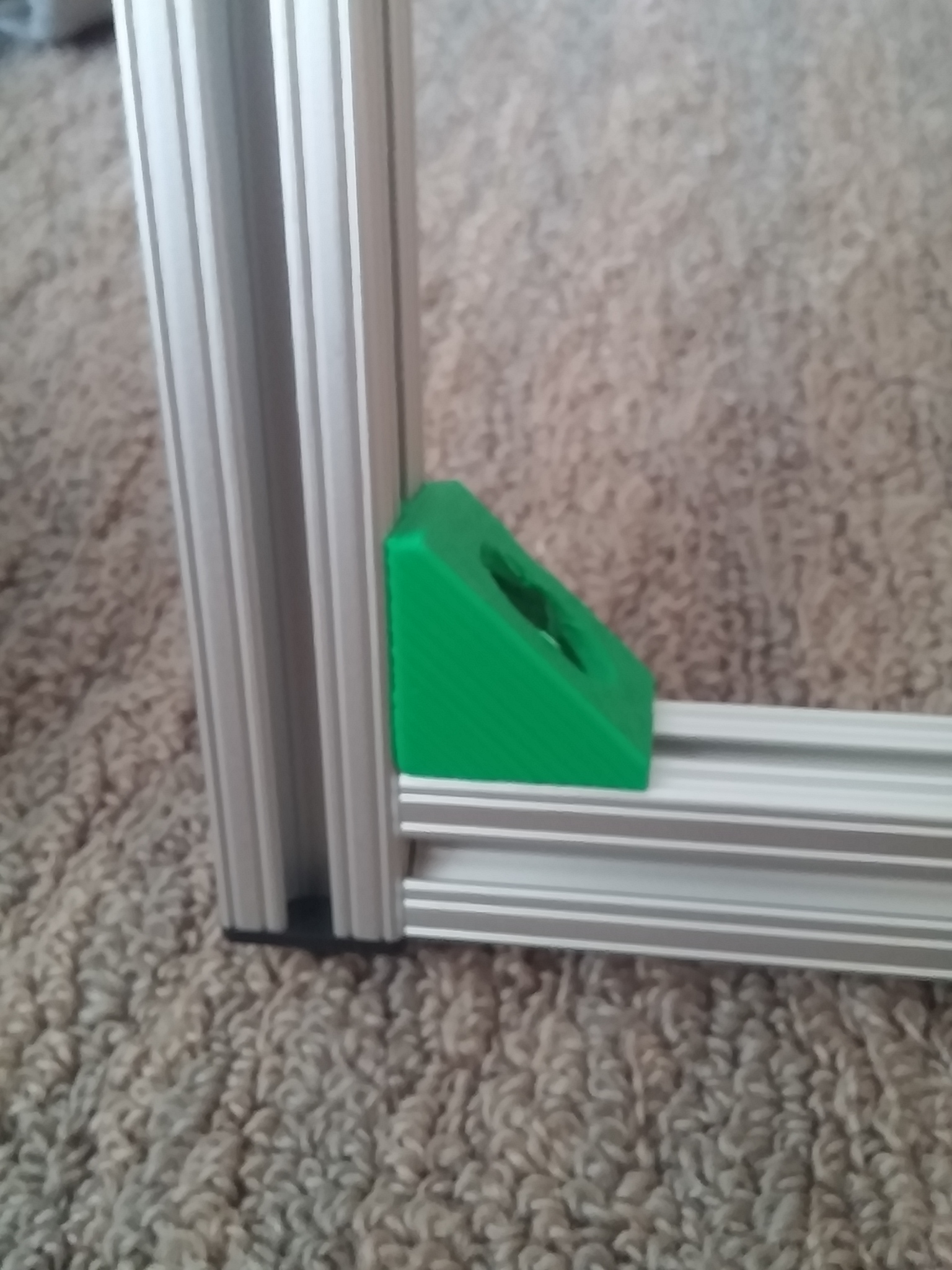
From left to right. 90 degree angle brackets for the Z-axis, mounts for the Z-axis guide rods, stepper motor coupler for Z-Axis, 608Z bearings for Z-axis ball screw and Y-axis drive rods.
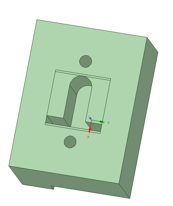
I got the linear slides in today March 24, 2015, been waiting on these to start the project. I ordered them on ebay from vendor in China so took awhile; couldn't justify the cost of buying locally. My first piece to be printed is bracket for Y-axis. I have the whole printer measured out, but I do not want to print anything ahead in case I need to mod something during the build.
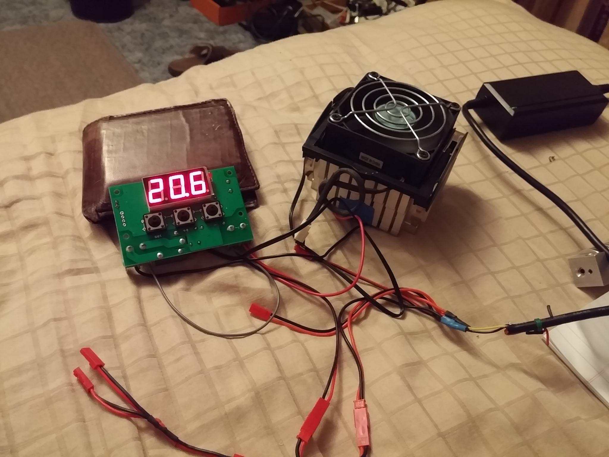
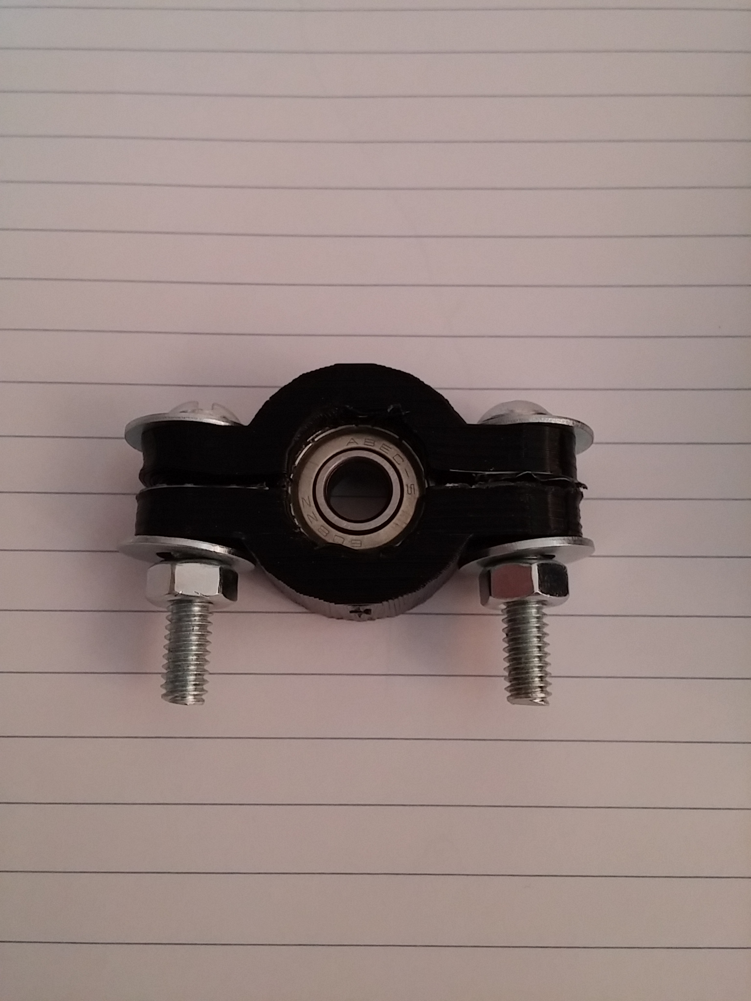
Testing out a peltiers for two applications; one as a heater for the heated bed using many of them. The other application is to use it as cooler for the motors. I may use two of them to cool the X and Y axis motors since they will be in the section of the printer that gets warm. The thermostat can be set for either heat or cool mode which is nice. The other two pictures I am stress testing some parts over time to see if they will crack. The one with nuts inside already had issues with separation so I brushed with some glue and am testing again.
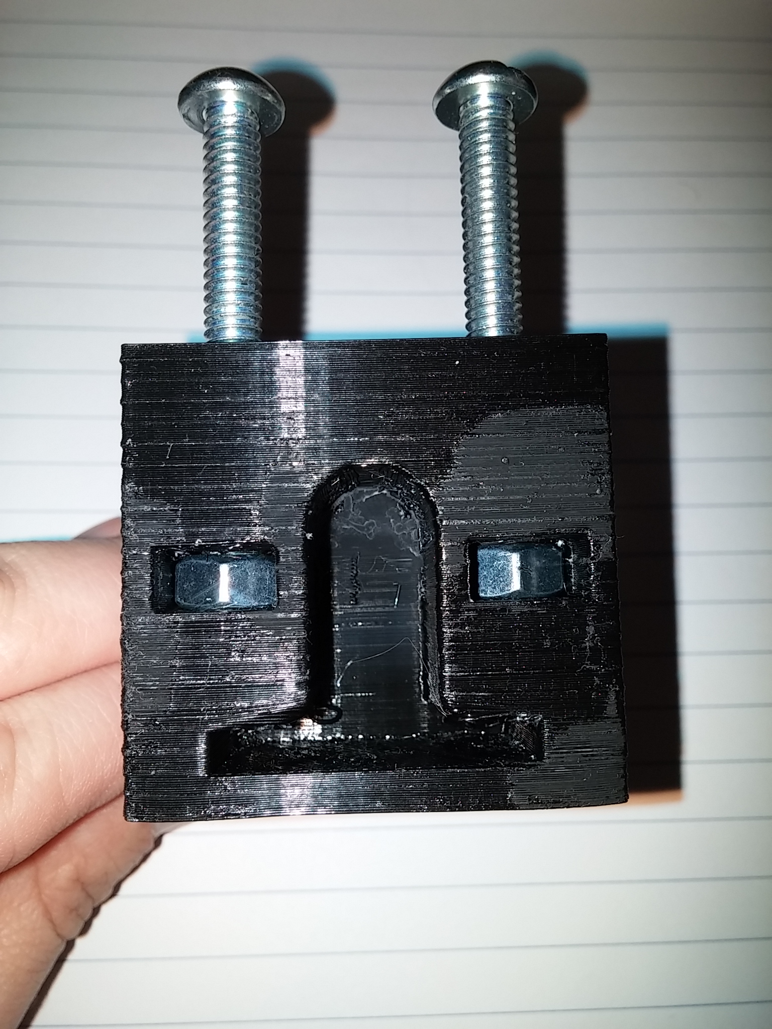
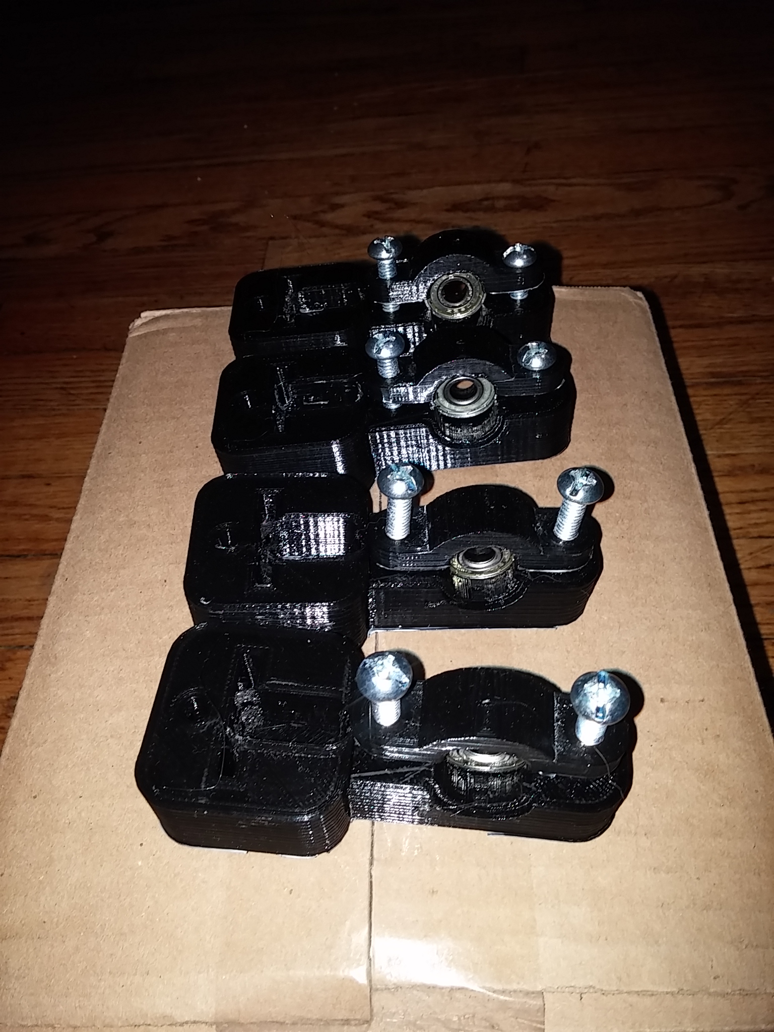
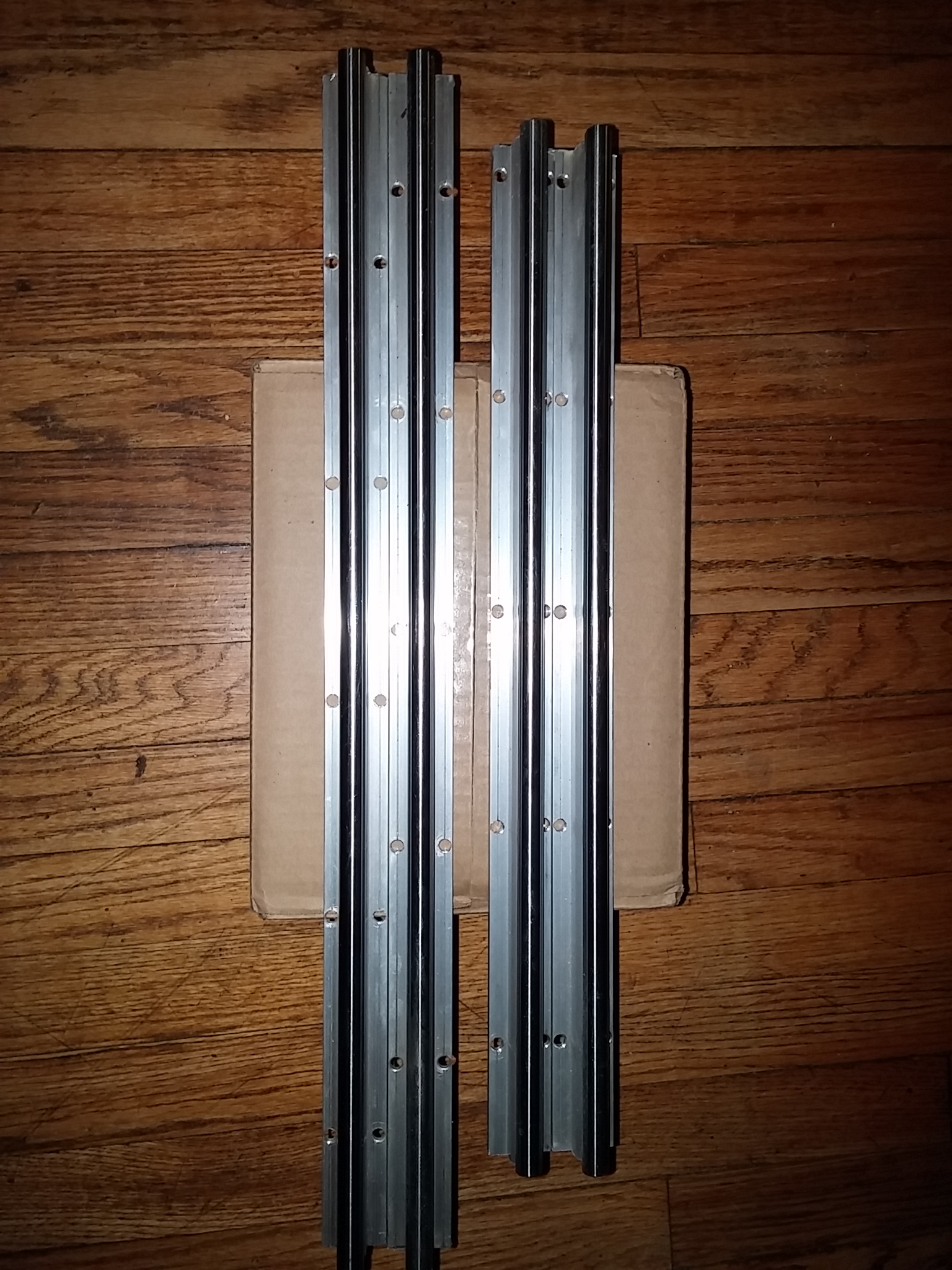
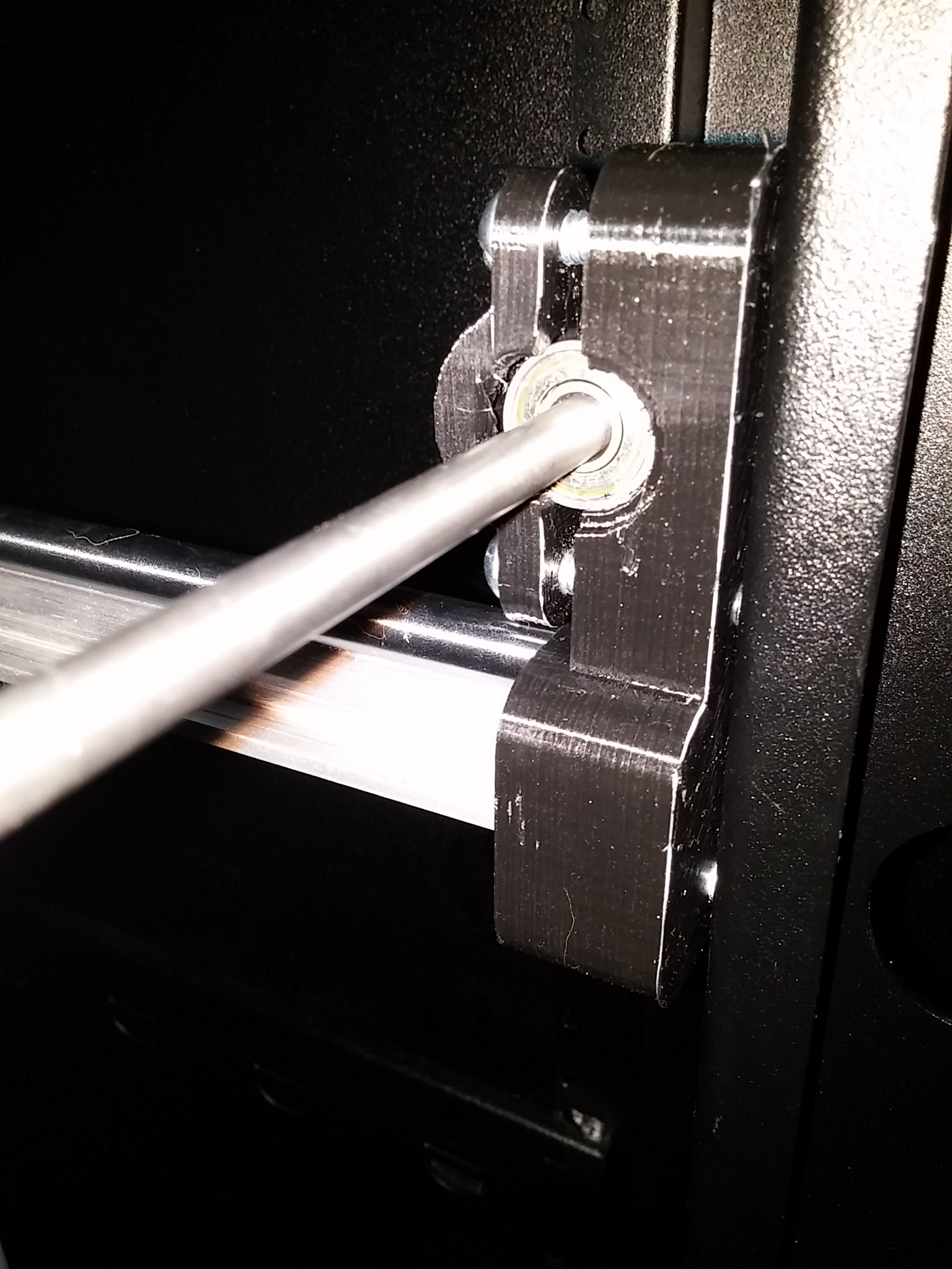
Printed the 4 Y-axis slide bearing mounts, included the bearings for the Y-axis drive shafts as well. I ended up redesigning these to include the drive bearings because I wanted them to be modular in case I want to move the entire X and Y assembly. I also made them so when you tighten the saddle clamps it will tension the belts, using lock nuts on the rail ensure they do not loosen up. I cut the two 1000mm slide rails into 4 pieces; two of them are 550mm and the other two are 450mm. This gives me the travel I want for the X and Y axis.
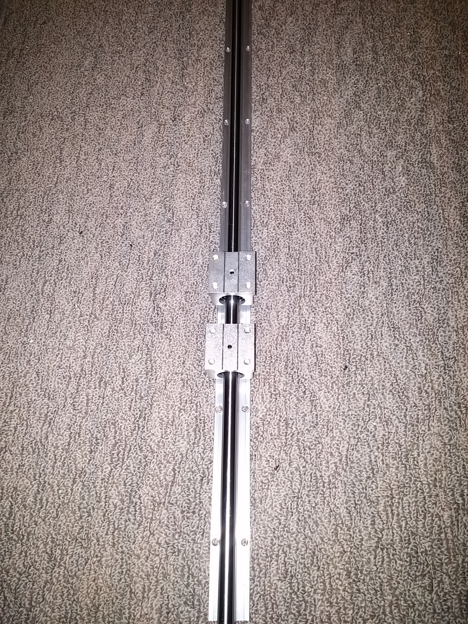
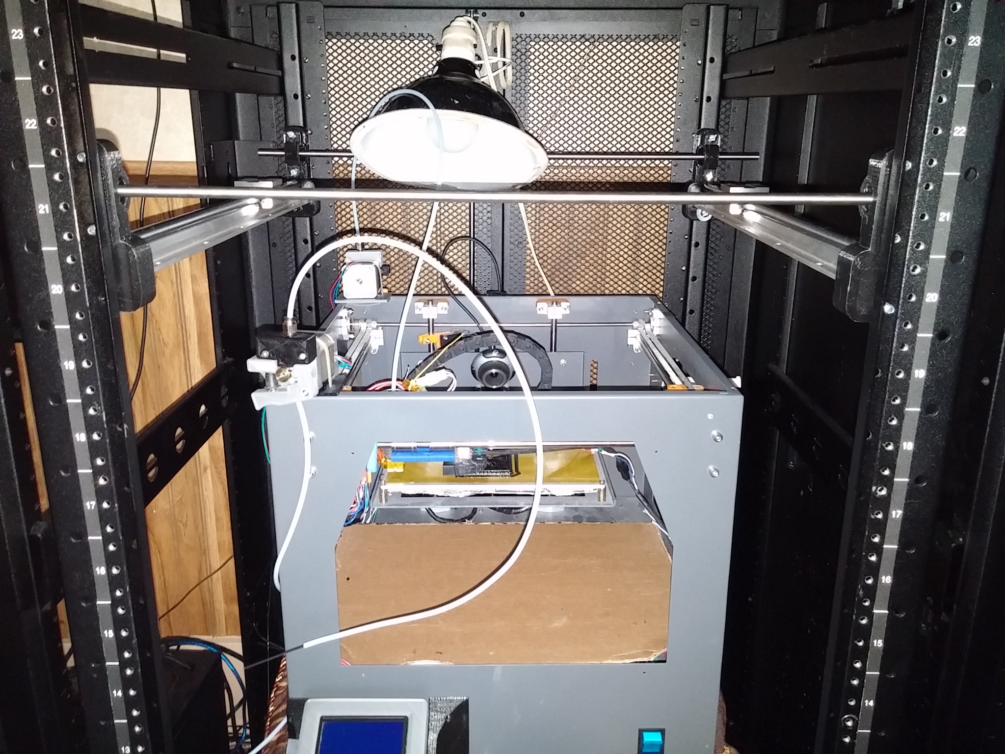
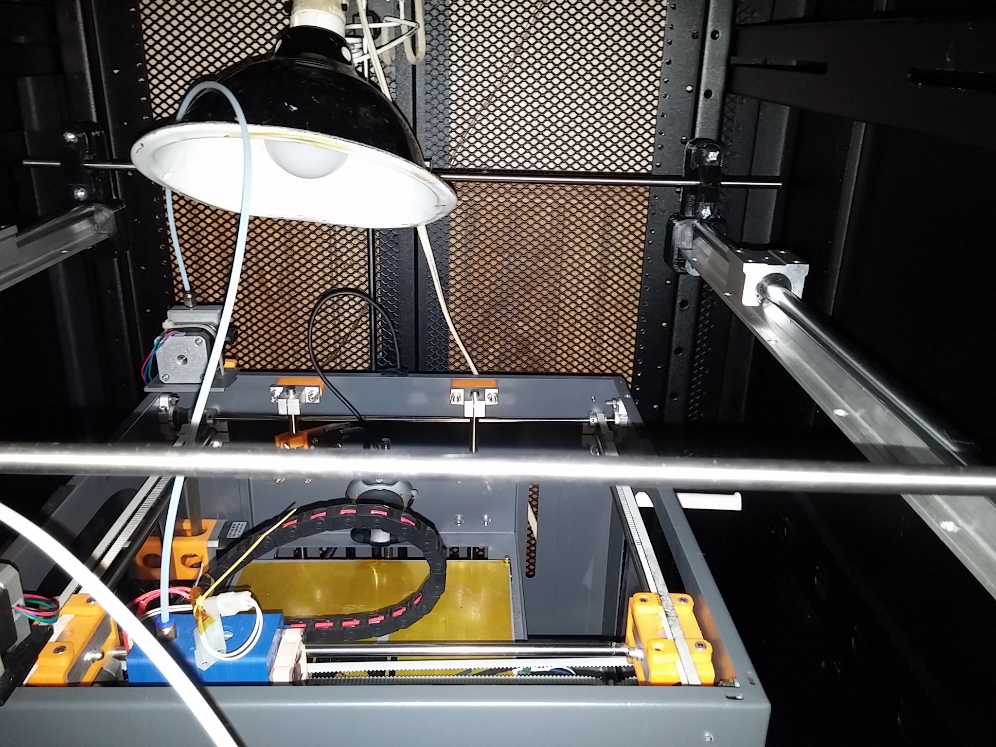
I have some prgress to report on the printer this morning of April 4, 2015; installed the Y-axis rails. I had the pieces done for a few days, but wanted to remeasure everything and make sure that a step now wasn't going to cause problems further into the project. Ignore the printer inside the cabinet below, its makes this build a little harder with it in the way, but its the best place for me to have it right now. So I am using the existing rail mount holes so the parts bolt right in, doing this allows the project to be completely modular. Using the standard rack mount holes also makes the project compatible with a wide variety of cabinets. Well I have to admit to my first try at this I made mistake and forgot the slide bearings, so had to pull them out and put the bearings on and reassemble. I made the mounts symmetrical so I can have a spare that will work in any of the four positions. You can see the saddle clamps are still loose I will tighten these up once I get the belts installed to tension them. Had to include this last picture, one of the reasons I need the printer enclosed, Zippy trys to get inside any chance he can get.
A quick update did a time lapse video of printing the X-Axis mount for the slide rails
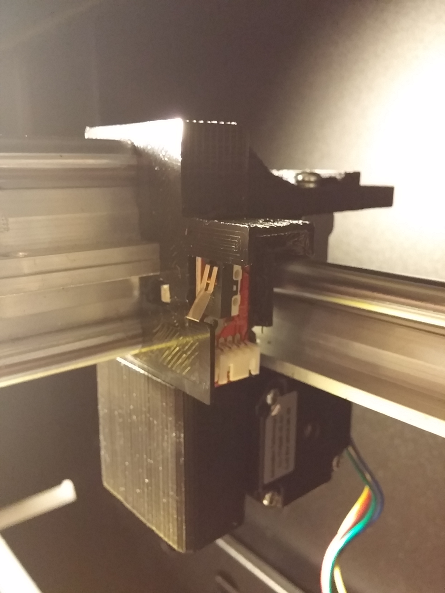
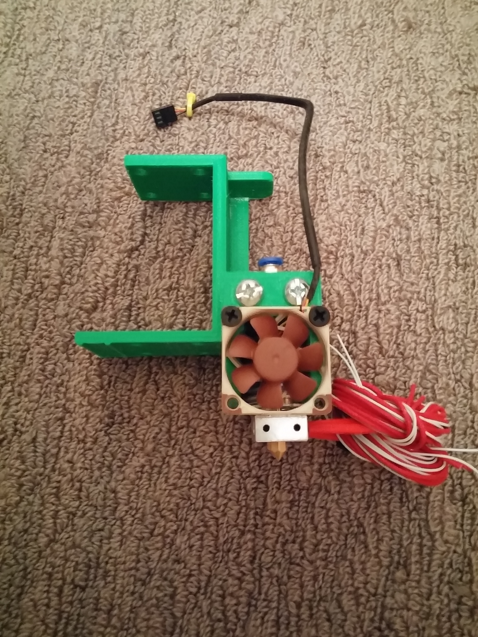
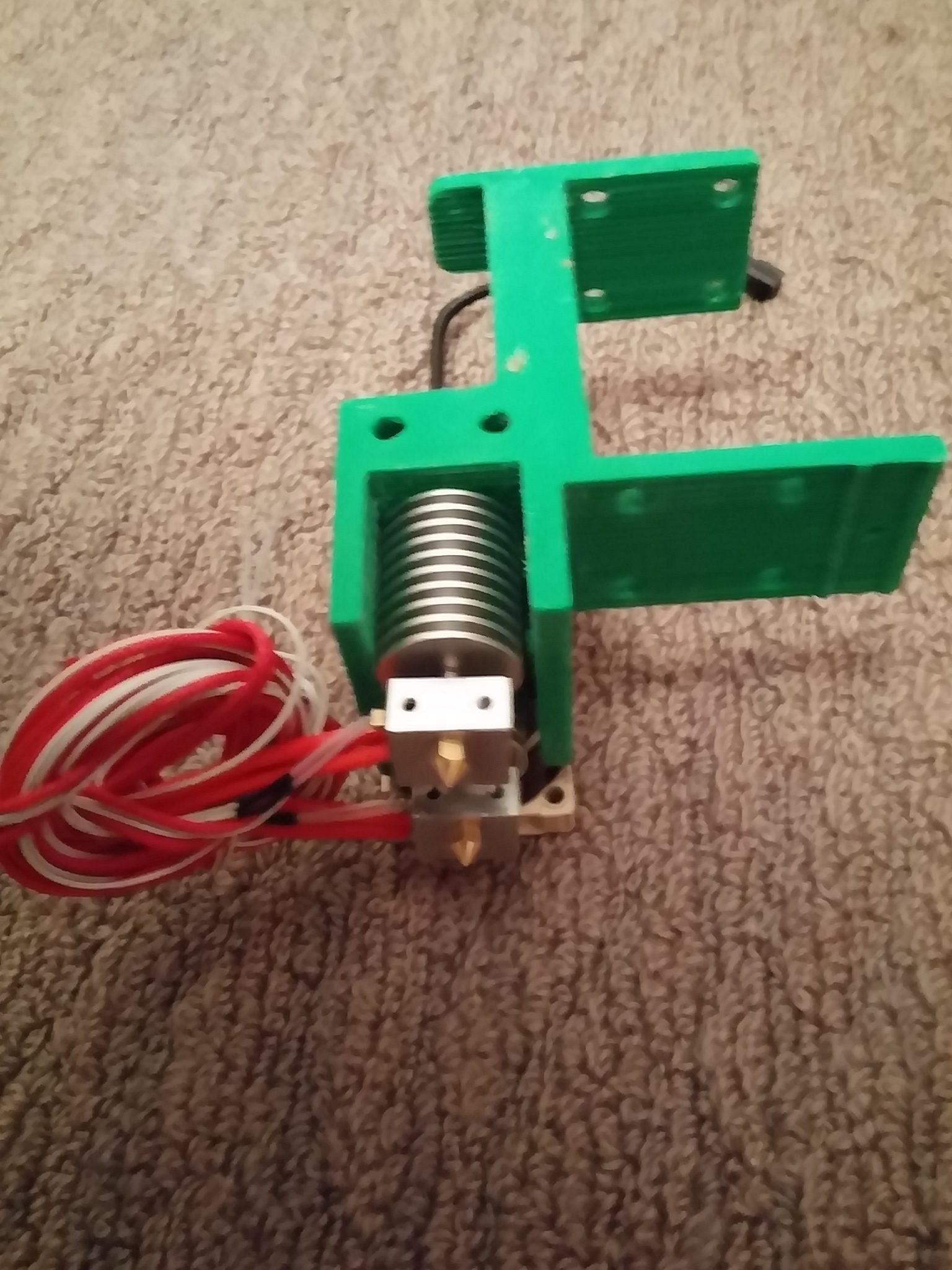
Quick update I have some more of the printer done. The Y-Axis is installed and tested with the RAMPS control board. Part of the X-Axis is installed, last two pictures are of the printhead mount. One side of the mount has a 40mm Noctua fan to keep the printheads cool. I need to get some plugs installed for the E3D hotends, so I can make them easier to replace.
April 22, 2015 A quick video of me assembling the X and Y axis into the cabinet.
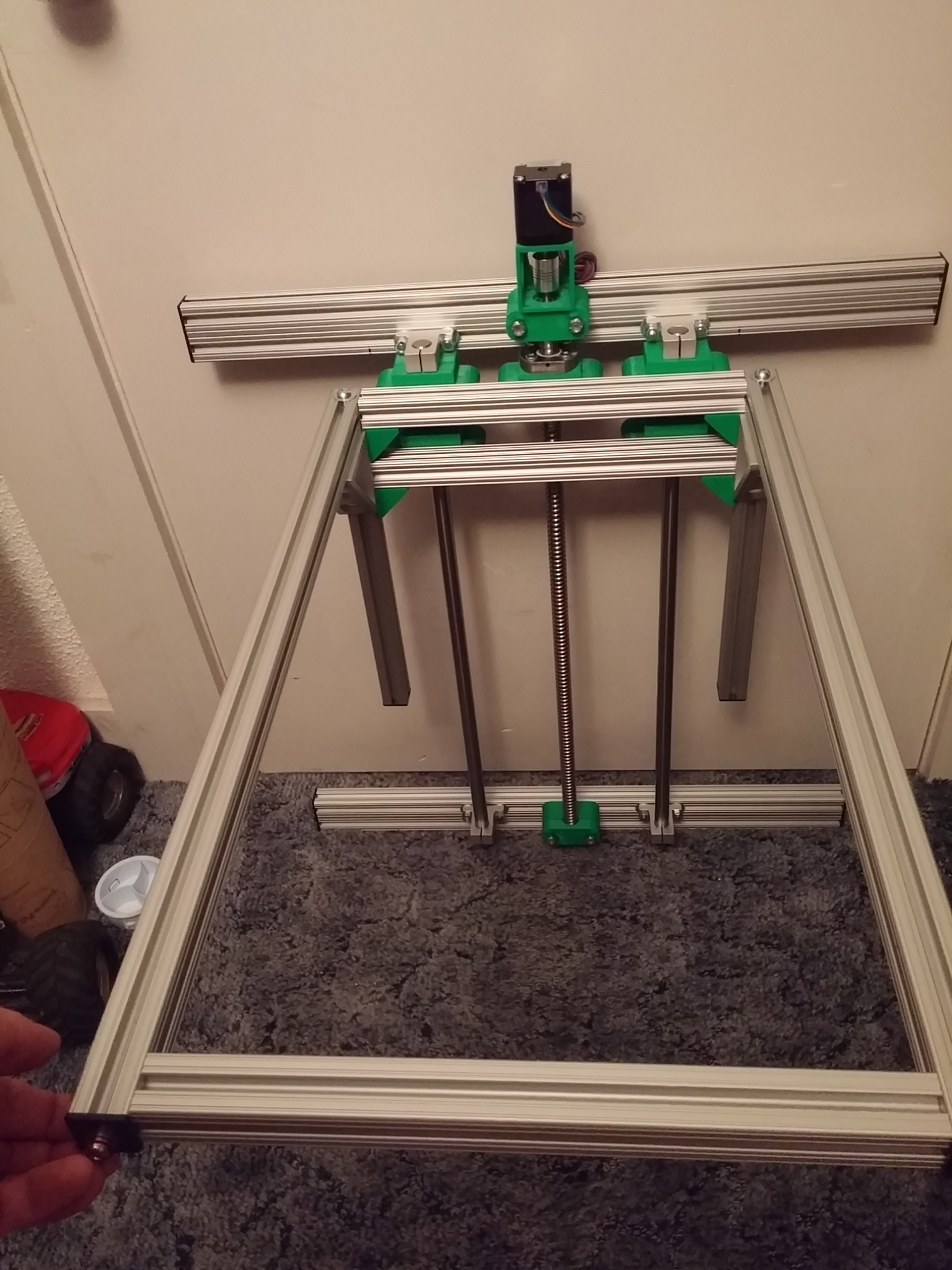
Got the Z-Axis print bed frame together. April, 26 2015 I am working on the 3d printed parts to connect up the lead screw and the two 16 mm linear rods.
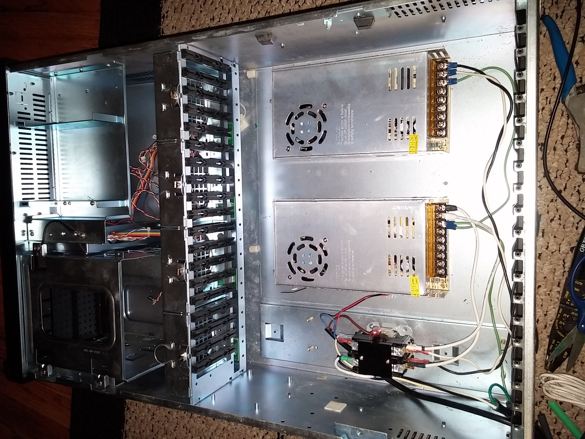
Buidling the power cabinet in an old PC case on the bottom of the Server rack.
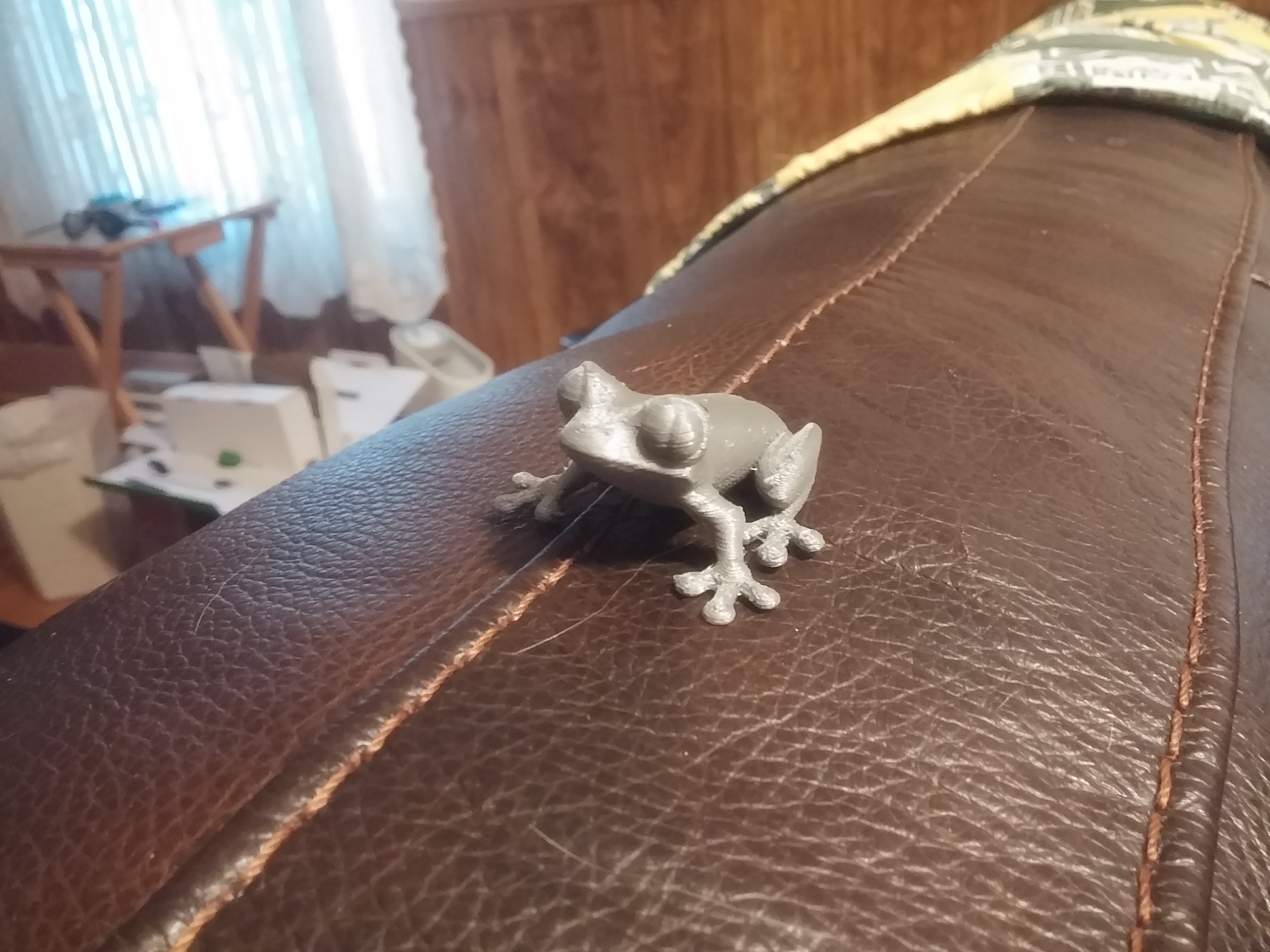
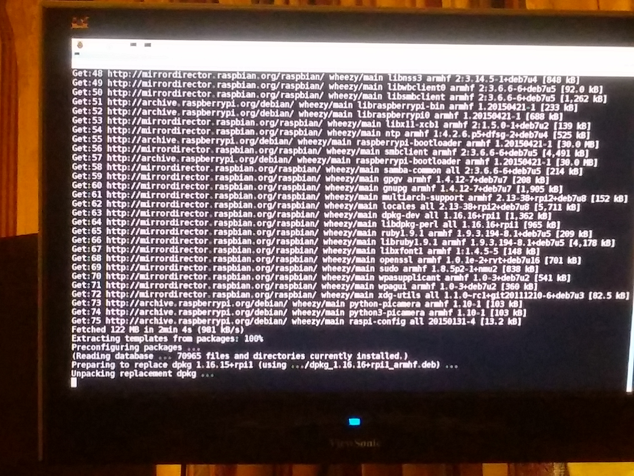
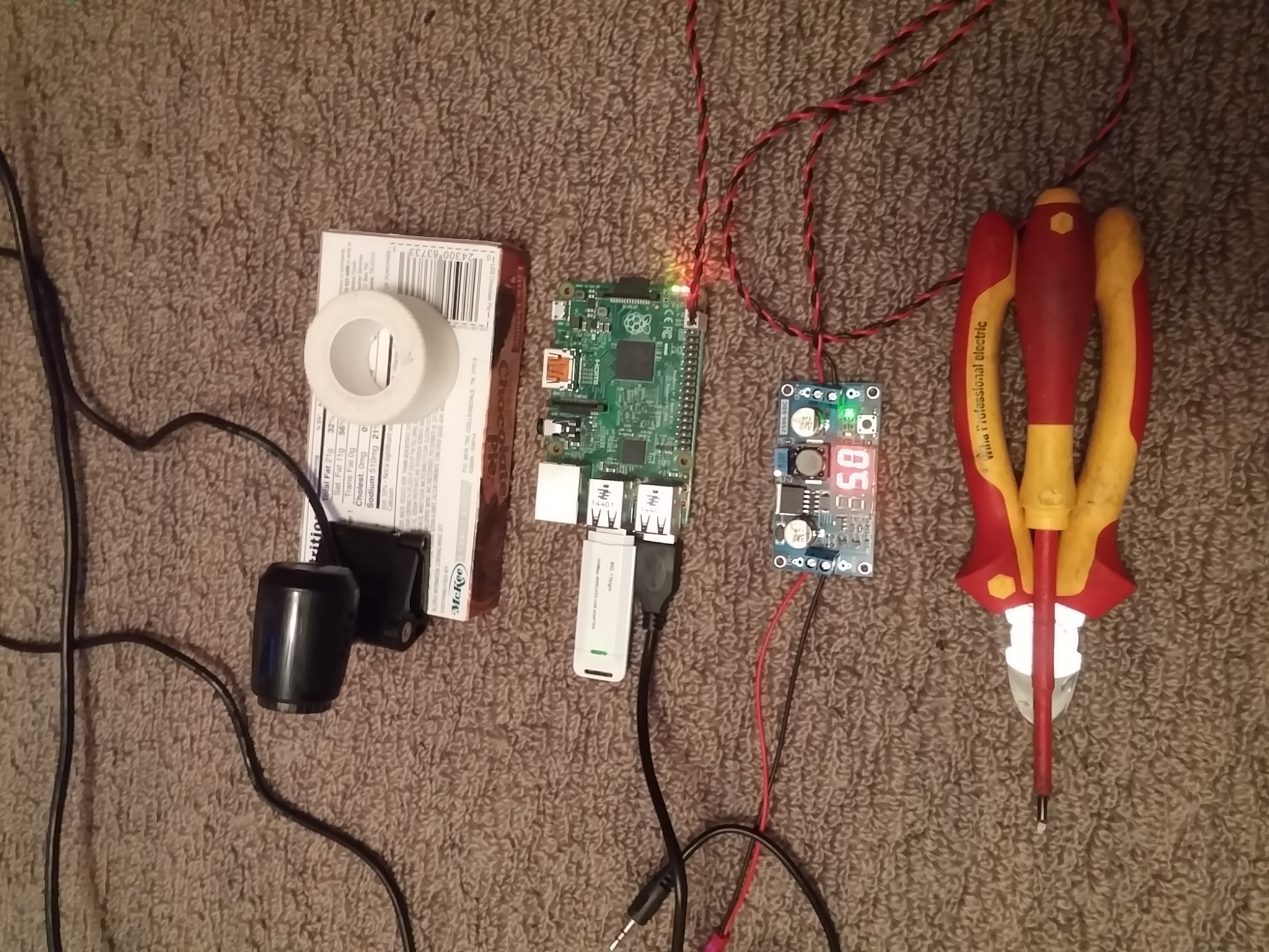
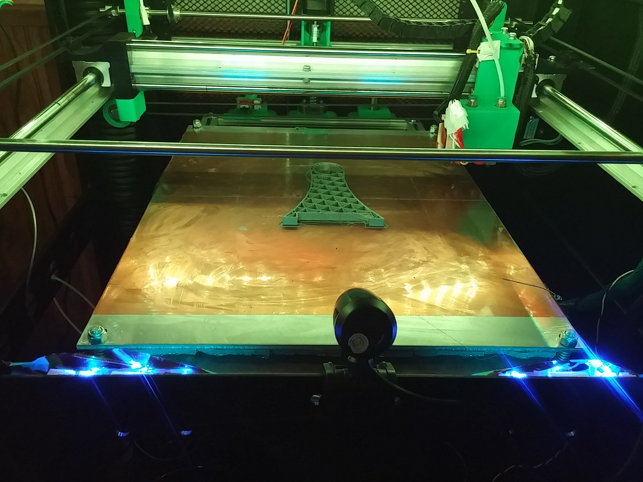
May 22, 2015 First print just a quick video and then the third print made a little tree frog printed out pretty nice. Now working on a Raspberry Pi project for the webcam server and control the printer remotely.
June 4, 2015 Just a quick update, found an article about my printer build on 3Dprint.com. It was kind of a surprise since they didn't mention it to me, but cool that they found my build. Here is a Link to the article.
![]()
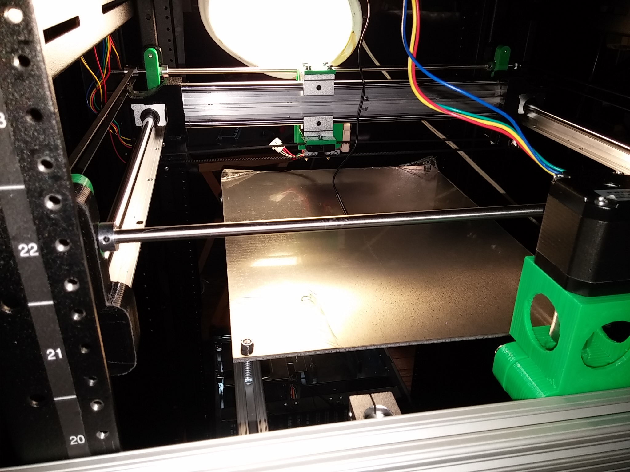
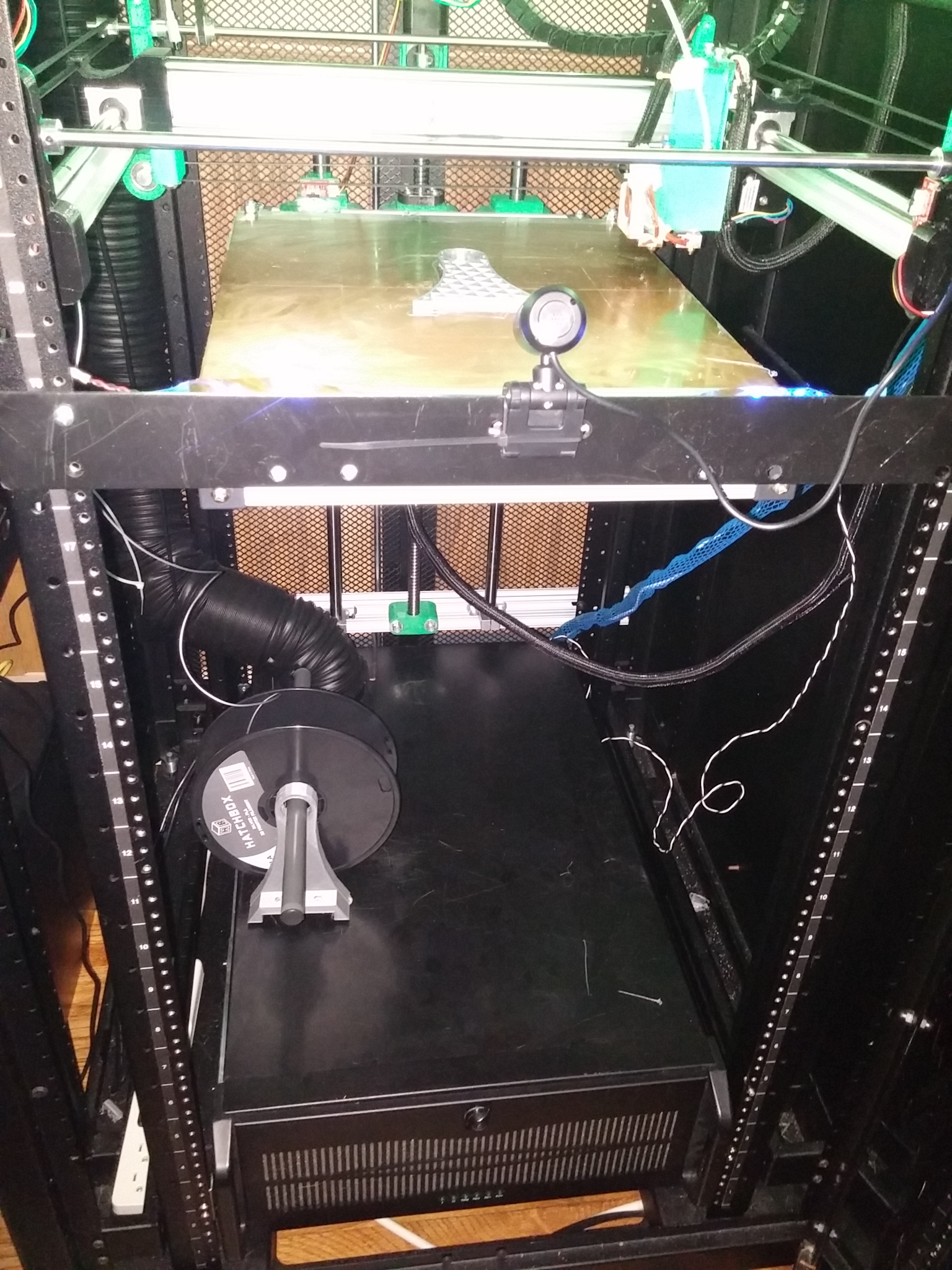
June 12, 2015 Just a quick update is are a couple pictures of the printer pretty much together, I still need to do some more wire manmagement, been twisting my control wires with the drill and running them through the webbing.
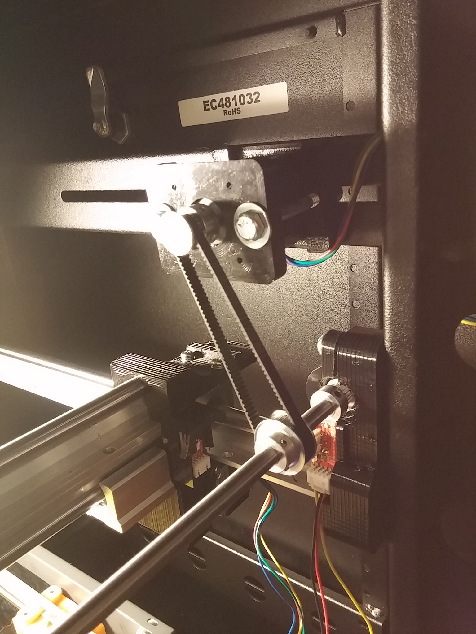
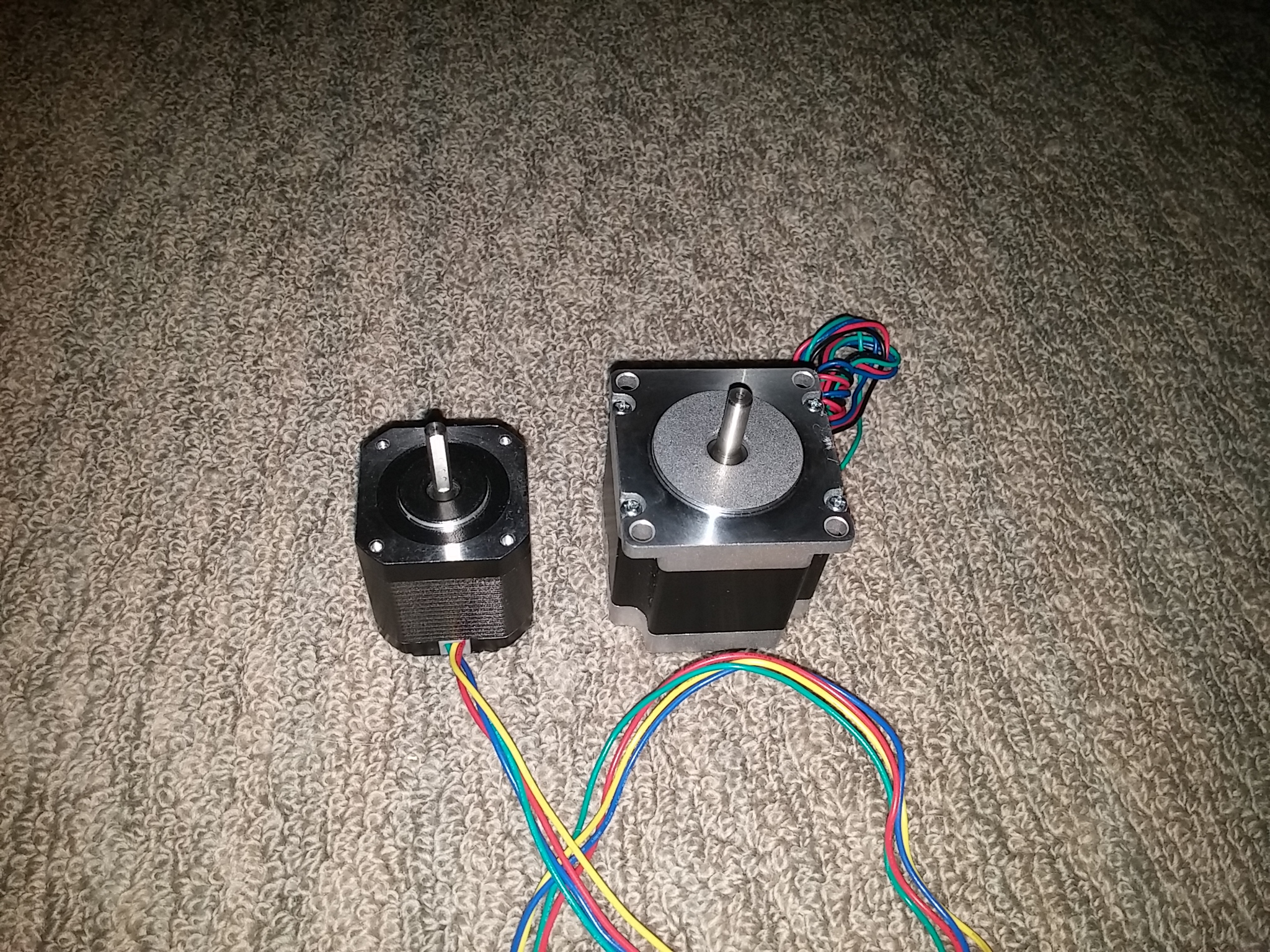
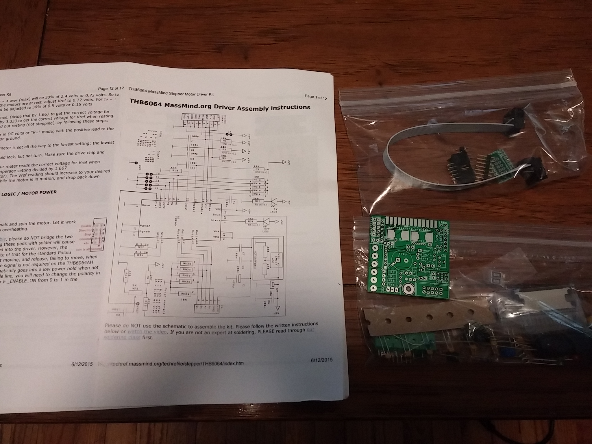
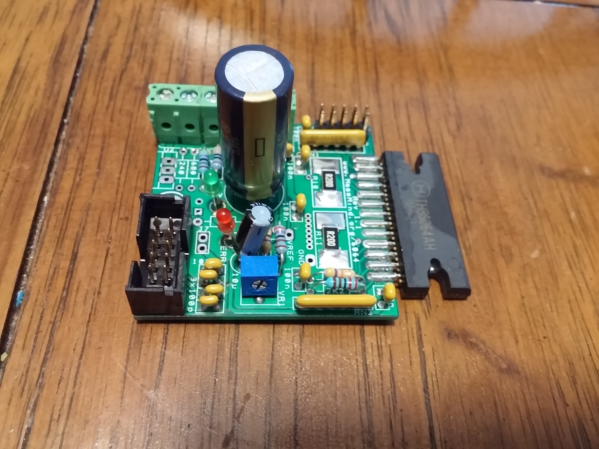
June 15, 2015 Well time to start the upgrades, I am upgrading to a Nema 23 stepper motor and external driver board for the Y-axis. The new external driver board is from www.MassMind.org
Its a little kit you get to assemble; which makes it allot easier to replace parts down the road if you feel more comfortable with the board. Also it says it can 1/64 step so that will give me better resolution on the heavier axis of my printer; which was pushing the limits it could handle with the Nema 17 and DRV8825 driver.
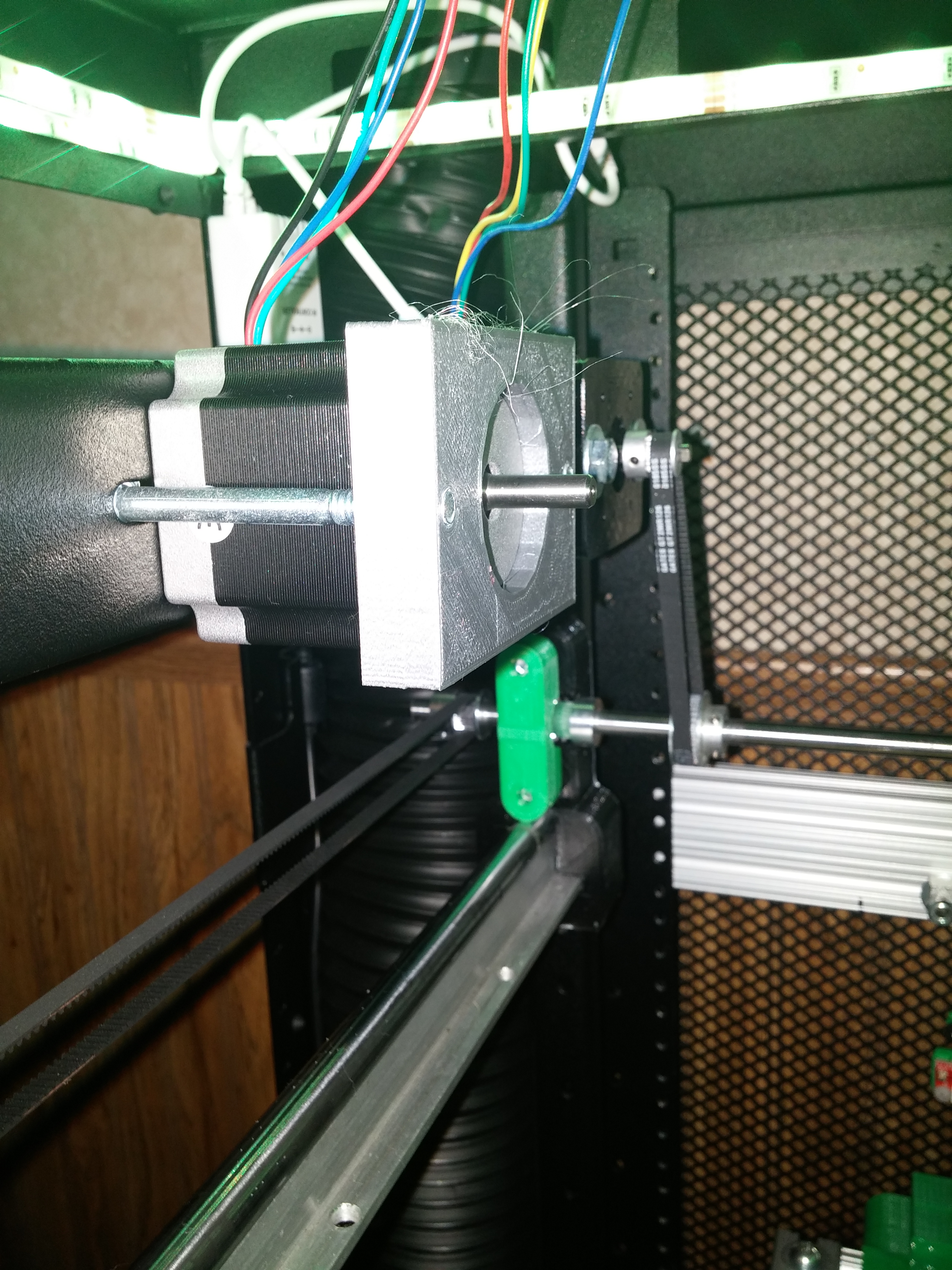
The motor on the left is the old Nema 17.
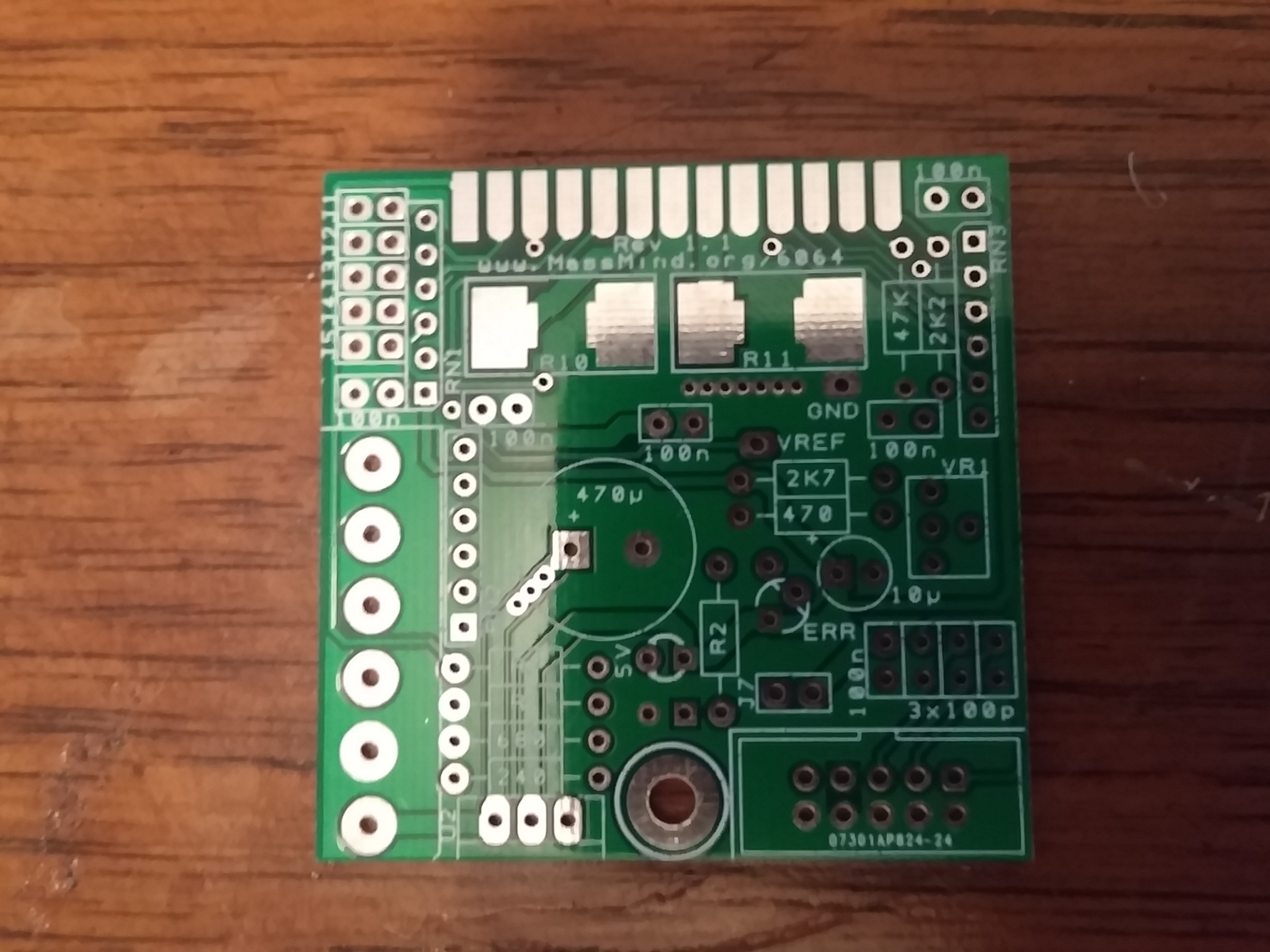
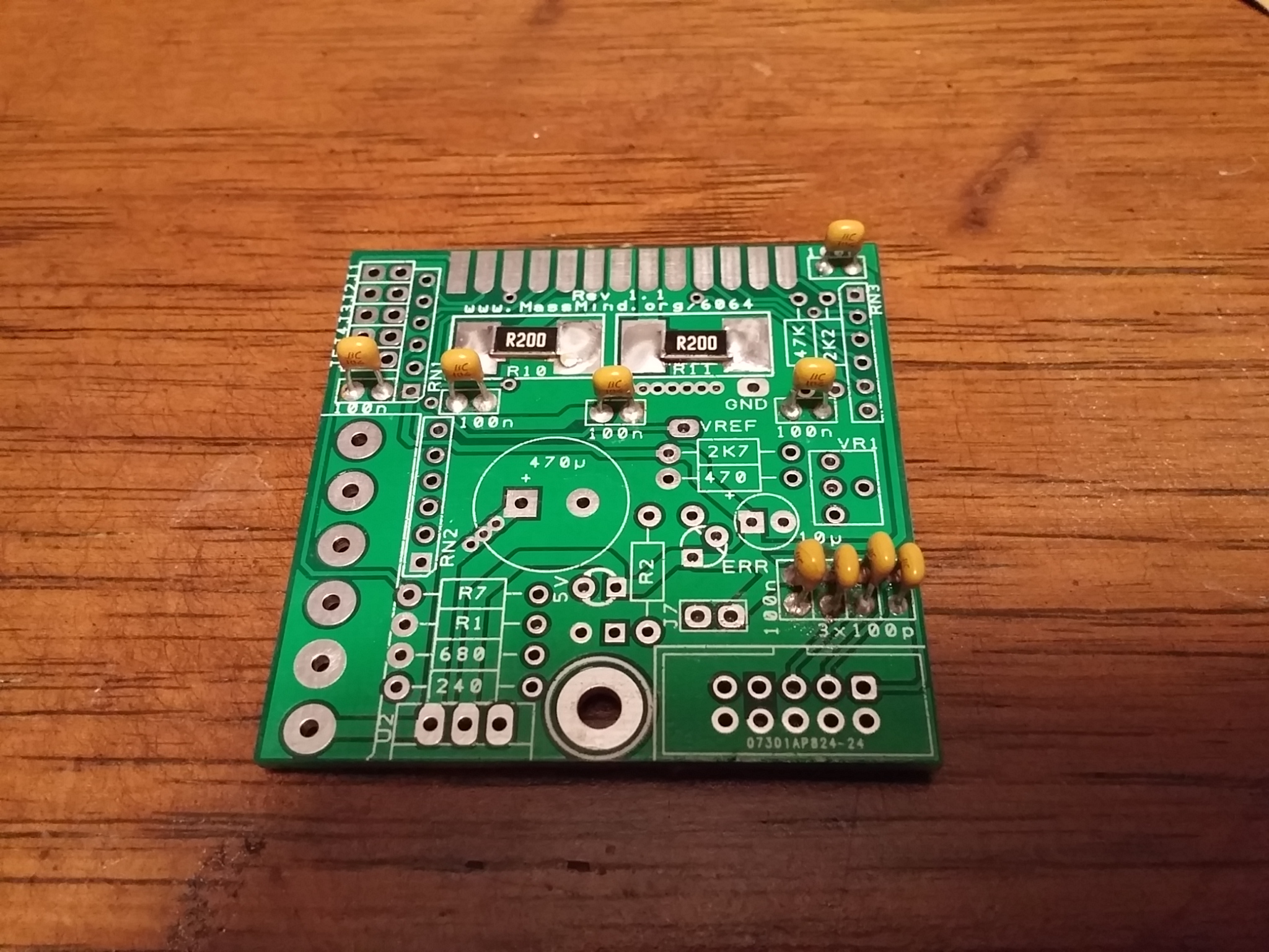
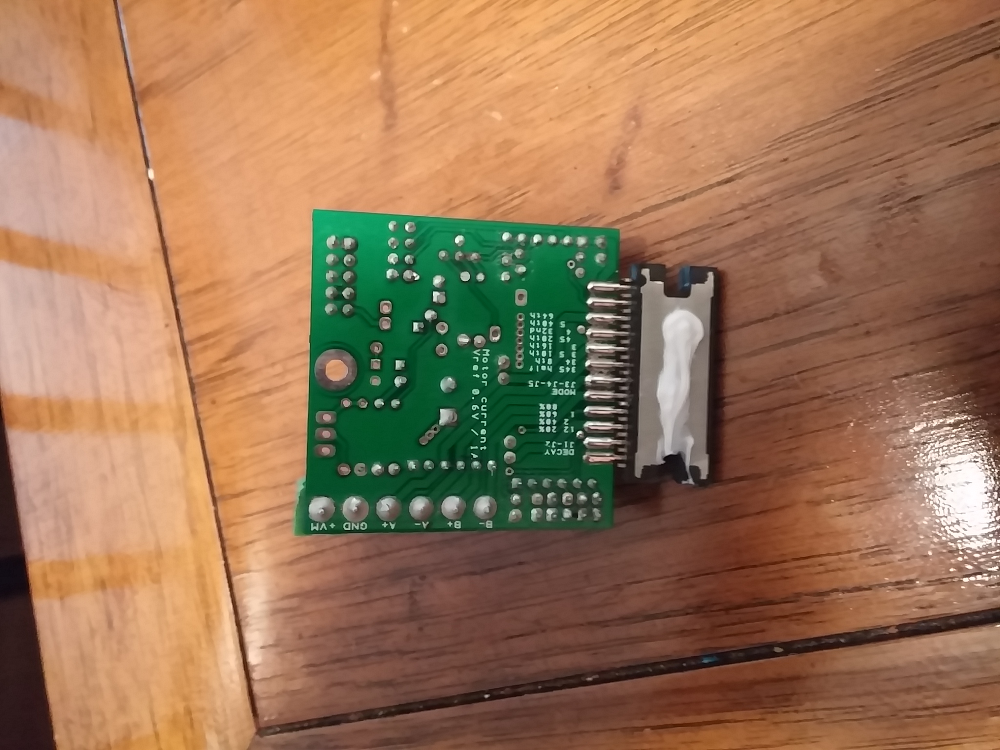
June 16, 2015 Got a few minutes tonight to work on the driver board assembly; I just need to solder on the main chip and mount it on a heat sink.
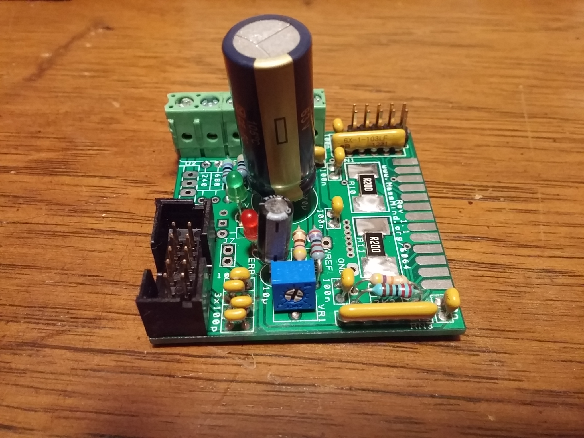
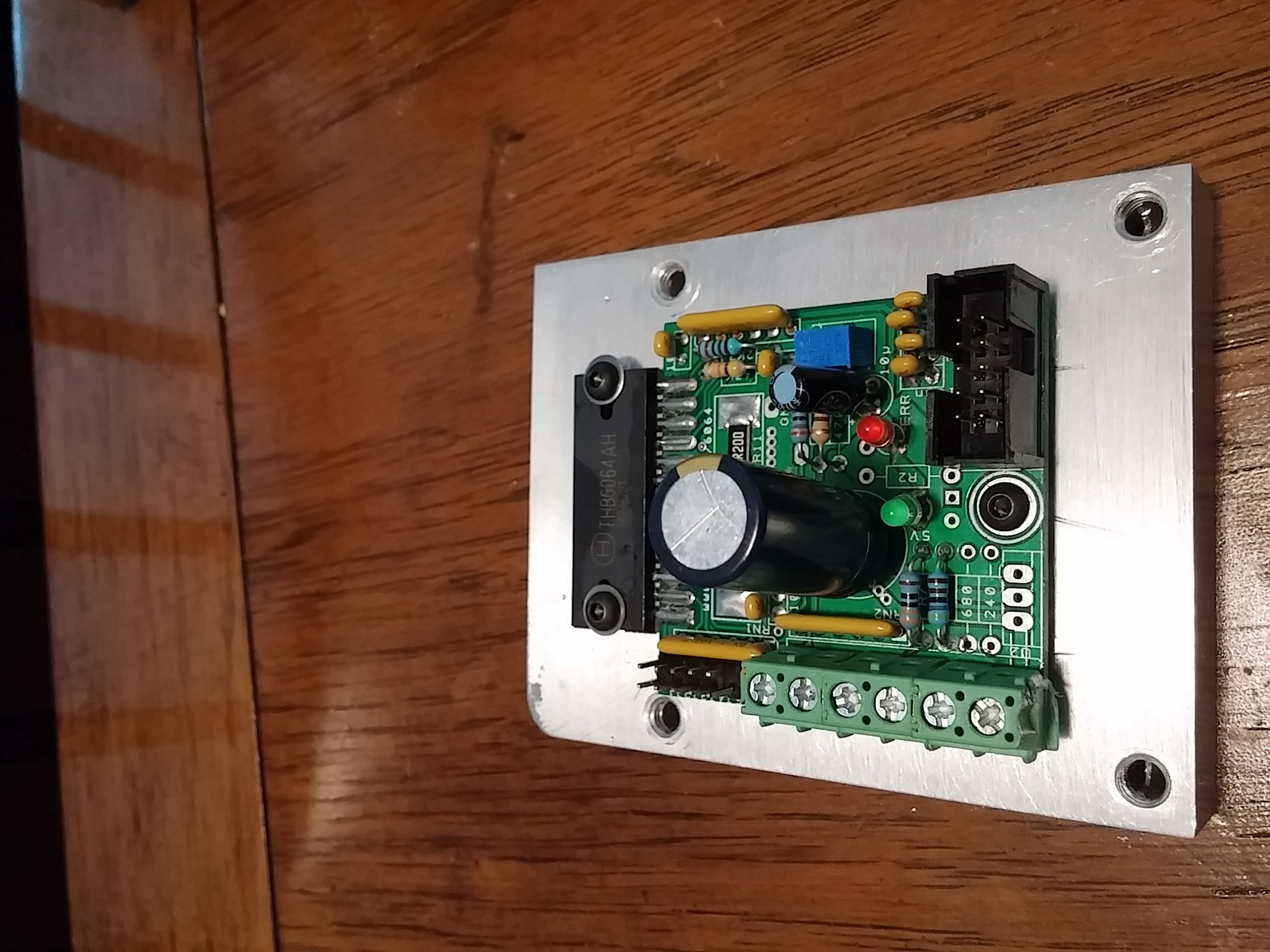
June 17, 2015 First tested out all the pins according to the instructions. I then installed the main chip, applied thermal paste, and installed on a heat sink I got out of my old X-box 360. Tested out board with a motor sitting on the bench using with the default settings on the install instructions no issues so far next step is to install the motor and test it out for real.
July 7, 2015 Back from Vacation and back to working its summer so spending most of my time outside, but getting a little of it done tonight. I ran the wires inside the printer and reconnected them. Using a mount I printed installed the stepper motor right next to existing Nema 17 motor. Tested it out and adjusted the power on the driver board, feels a little rough right now; so next step is to fine tune it a little more.

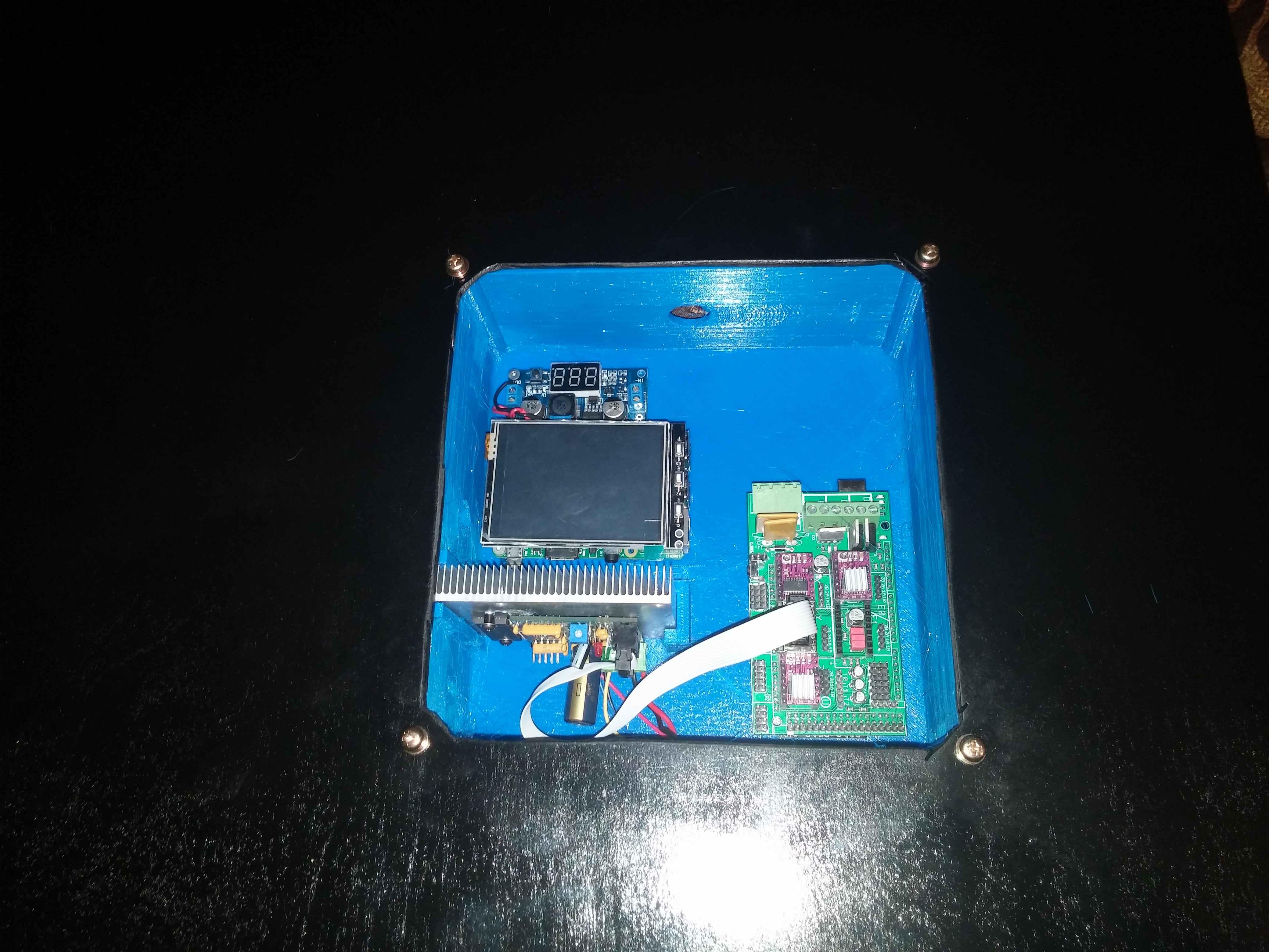
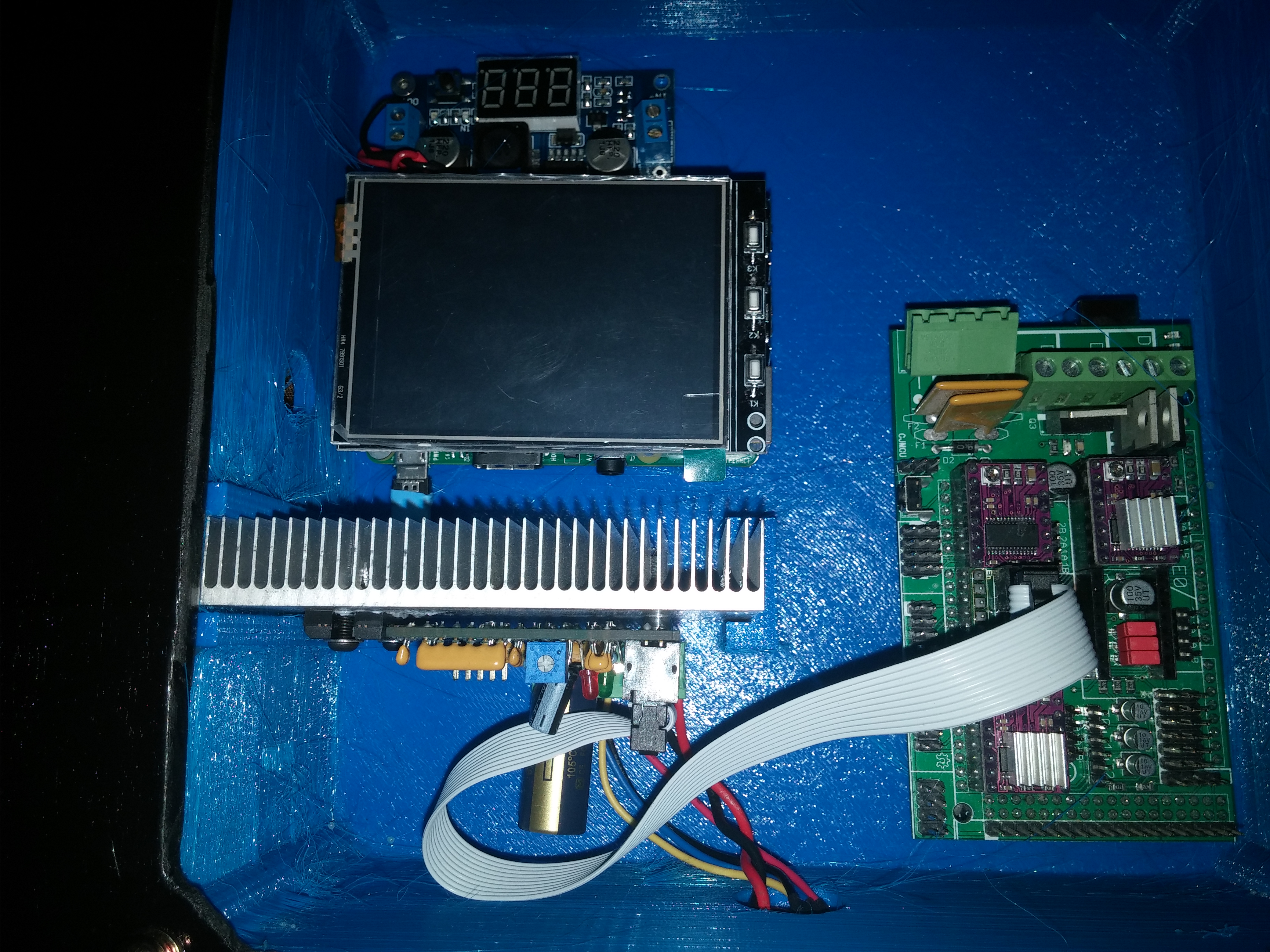
Sept 14, 2015 Finally getting back on the project, these are pictures of the Electronics box before running all the wires to the boards. This box is the biggest print I have done and really took some extra work to get it to print correctly. I added cooling to the steppers and extra cooling was needed for the electronics as well.